|
|
|
|
Building a simple Lehman seismometer
(This device is covered in my book.) |
|---|
|
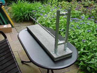
When my girl friend and I went to the FPGA-2001 conference in Monterey and decided to stay for an additional week in the USA, we made a short trip to the Berkeley campus where I saw a wonderful old seismometer on display at the geophysics department. This was the moment I started to think about how to build my own seismometer (and connect it to my VAX :-) ). After digging through my collection of Spektrum der Wissenschaft issues (the German version of Scientific American) and reading many interesting web pages from other people interested in seismometers, I decided to build a simple Lehman type seismometer which is shown in the following three pictures as a first impression. (In these pictures neither the damping mechanism nor the pickup coil or the magnet are shown. These topics will be covered later.) |
|
A seismometer is a measuring device which translates slightest movements of the earth into (preferrably) an electrical signal which can be recorded and processed for example. (It should be noted that early seismometers were completely mechanical devices which translated small movements into larger motions which could be written by a strip chart recorder. The device on display at the Berkeley campus is of this type, for example.) A Lehman type seismometer consists basically of a horizontally mounted, weighed boom which can swing freely on one end. This motion is usually detected by a coil mounted on the free end of the boom which is seated above a quite strong magnet. Each movement of the boom is translated into an induced voltage in the coil which can be amplified, filtered and recorded or online processed after passing a suitable A/D converter. |
|
|
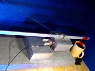
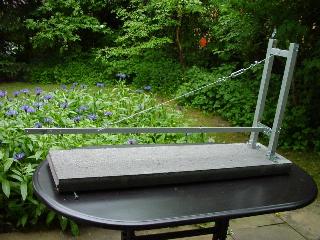
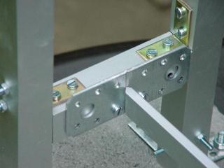
As can be seen in the figures above and on the left my seismometer is built from aluminium bars (obtained from a local hardware store) which are mounted onto a stone plate. The horizontally swinging bar rests on a knife edge that is held against a stable base plate located between the two vertical aluminium bars. This knife edge is shown here in the picture to the left. This knife edge is a crucial part of a seismometer since it determines the amount of force necessary to move the boom out of its rest position. There are in fact better ways to accomplish this than using a knife edge - one could, for example, use a wire string for this connection, too, a method shown here. |
|
The other side of the swinging boom is hold up by a wire of guitar string which is fastened on top of the mounting frame. Since it is a quite tedious task to adjust the tilt angle of the boom by reattaching the guitar wire over and over again, I decided to use parts of a steel guitar to make the necessary adjustments as easy as possible. The main problem with this type of seismometer is the fact that the boom is a pendulum and will swing with its own time constant as soon as it is excited by a seismic event. So after the boom starts swinging, the measurement will mainly show the natural movement of the pendulum instead of the more interesting movement of the earth. To avoid this there has to be some damping of the boom, which can be done in a variety of ways - for example using an aluminium plate moving between the shoes of a horseshoe magnet or by moving a small plate in an oil bath. |
|
|
Since the calibration of a damping circuit using a plate swinging in an oil bath is much more simpler to control and to adjust, I decided to use this technique in my seismometer. Most Lehman type seismometers are so called "long period" instruments which means that the natural period of the pendulum is about ten to twenty seconds in duration. (A short period seismometer has a time constant of about one second.) Adjusting the peroid of the boom by filling the damping oil bath is quite time consuming but not a very difficult task. :-)
On the right is the oil bath :-) with the paddle which is damping the movement on the freely swinging end of the boom, while on the left the mass attached to the boom can be seen. |
|
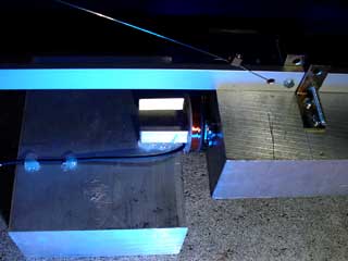
The picture to the right shows the freely swinging end of the boom with the attached mass and the pickup coil which is used to detect the small movements of the pendulum. Since each additional wire which is necessary to connect electronics mounted on the pendulum changes the characteristics of the guitar wire and thus the free period of the pendulum, I decided to mount the magnet on the mass of the pendulum while the pickup coil is mounted on the base plate. This coil and the rare earth magnet (obtained from a scrapped 3.5 inch disk drives head actuator mechanism) can be seen in the middle of the picture. The gap between them is about 1mm. On the right the supporting guitar wire can be seen being attached to the boom. |
|
|
|
The picture on the left shows the overall design of the pickup and damping system of the Lehman type seismometer. From left to right, the pickup coil, mounted on a solid aluminium block (with hot glue) which is placed onto the supporting stone plate, the rare earth magnet mounted onto the pendulum mass and the oil bath used for damping the system, can be seen. |
|
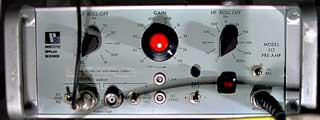
The next problem is the amplification of the signal induced in the pickup coil by the small movements of the free swinging side of the pendulum boom. Since the instrument is a long period seismometer an DC (or at least nearly DC) operational amplifier is necessary to avoid losing interesting very low frequency information. On the other side it is necessary to use a low pass filter to get rid of "high frequency" electric noise as generated by the power grid system, etc. |
|
|
|
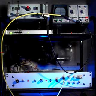
On the left the complete equipment which is necessary to amplify the signals generated by the pickup coil, convert the resulting voltages to digital signals and to transmit these values to a computer system, can be seen. The operational amplifier with its integrated high and low pass filter electronics is located on the upper left corner. The amplified signal resulting from this stage of processing is fed to a small oscilloscope (in the upper right corner) and from there to the eight channel A/D-converter (only the first channel is used until now, but a three axis geophone is the next project, so eight channels seemed to be a good compromise between cost and the ability to expand the system). The A/D-converter transmits the resulting values by a serial line to one of my VAX systems which is located in another room. The device sitting under the amplifier is a leased line modem which is connected to its counterpart in the computer room. |