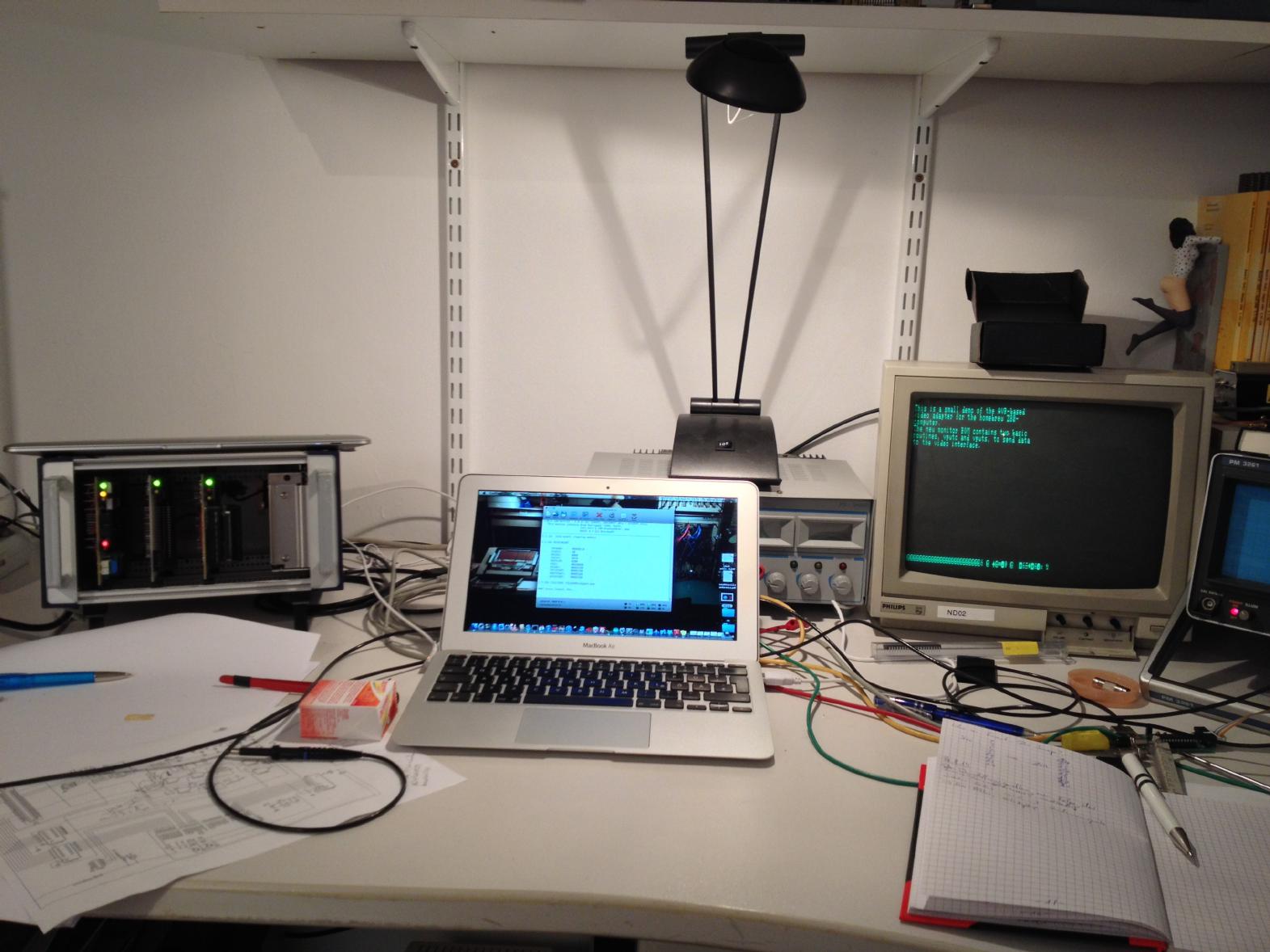
Now that the homebrew Z80 computer is working like a charm, something was still missing... ...a video interface! :-) Last weekend my friend Ingo Klöckl came for a visit and as always on our "meet-and-geek"-weekends, we try to build or program something interesting. This weekend we decided that the time was ripe for developing a video interface. Some preliminary thoughts showed that building one using TTL chips would be feasible (and stylish :-) ) but required to much work to be done in a single weekend. Accordingly, we decided to adapt the AVR-based video controller built by Grant Searle which in turn is based on an earlier design by Daryl Rictor. This approach had two advantages: It requires much less circuitry than our envisioned TTL circuit and it was THE opportunity for me to get some experience with AVR-processors. The idea of this video interface is brilliant: Generate all of the timing not in hardware, which is cumbersome due to the strange column and row counts, but in software running on an AVR-processor. Using a sufficiently large AVR-processor, there is even enough on-chip RAM for the video RAM. So a very basic setup would only require the AVR-processor, an eight bit shift register, a 16 MHz oscillator and two resistors for generating the video signal from a TTL synchronisation signal generated by the processor and the TTL output from the shift register. |
|
|
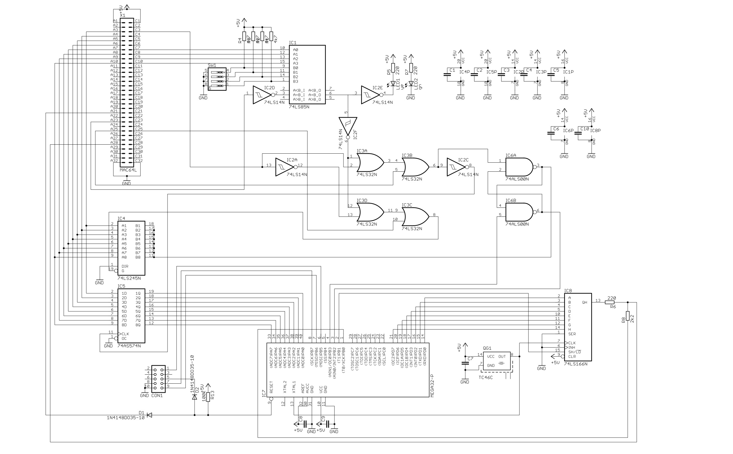
The picture on the left shows the schematic for the video controller: In the upper left the 64 pin bus connector for the Z80 backplane can be seen. The 74LS85 with the four position DIP switch is used as an IO-address decode and generates an active-high select signal on its pin 3. This signal controls a LED mounted on the front of the circuit board as well as the remaining interface logic. The video signal generator circuitry is located on the bottom of the schematic. It consists of the AVR-processor itself, a 16 MHz TTL oscillator, a 74LS166 shift register and two resistors (220 and 2200 Ohms). The bus-interface itself is simple: It consists of a 74LS574 octal latch which can be loaded from the Z80-CPU by an appropriate out-instruction. Loading this register also sets a simple RS-flip-flop built from two 74LS00 NAND-gates (right hand side). The output of this flip-flop is sampled by the AVR-processor to determine if new data has arrived. On the other hand, the status of this flip-flop can be read back by the Z80-CPU to determine whether the AVR-processor has already processed the data stored in the 74LS574. This is accomplished by an eight bit bus driver 74LS245. The remaining circuitry performs the necessary address- and control signal-decoding, generating an active-low enable signal for the 74LS245 and a clock signal for the eight bit latch 74LS574. |
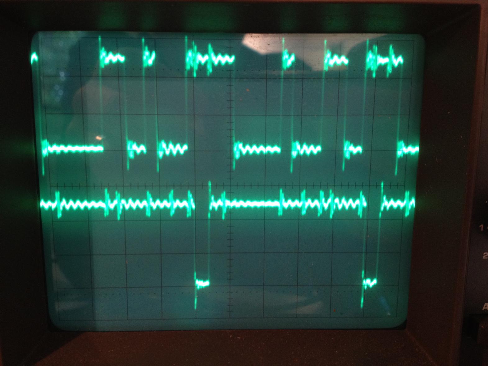
| As simple as this bus-interface is, it did not work initially due to a wiring error of mine. The picture on the right shows the behaviour during a write access to the eight bit latch 74LS574. The two traces show the active-low select and write-enable inputs to the quad OR gate 74LS32. I miswired these so that a write access would have affected the 74LS245 while a read-access would have activated the 74LS574 which is exactly the wrong way around. These accesses were altogether blocked by ORing the resulting signals with the /WR- and /RD-signals from the Z80-CPU. The oscilloscope screen-shot on the right brought me on the right track - fixing this wiring error was a matter of minutes. |
|
|
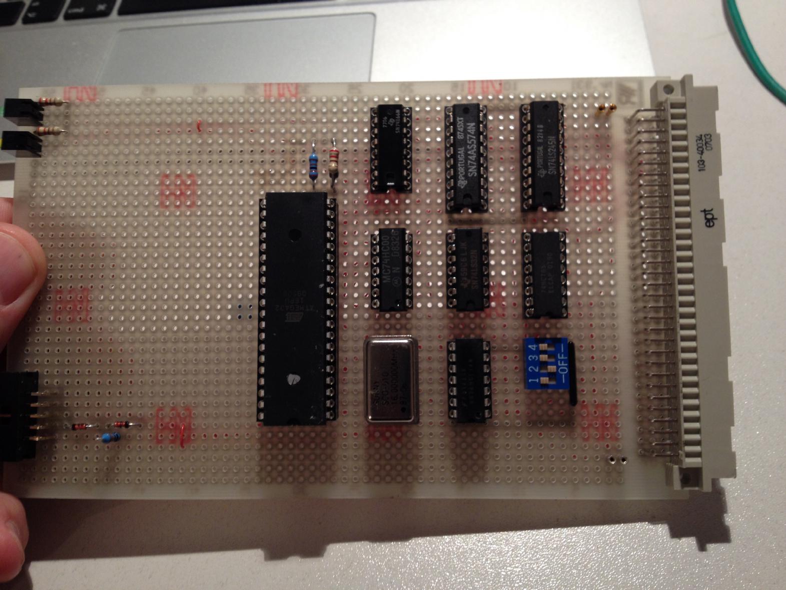
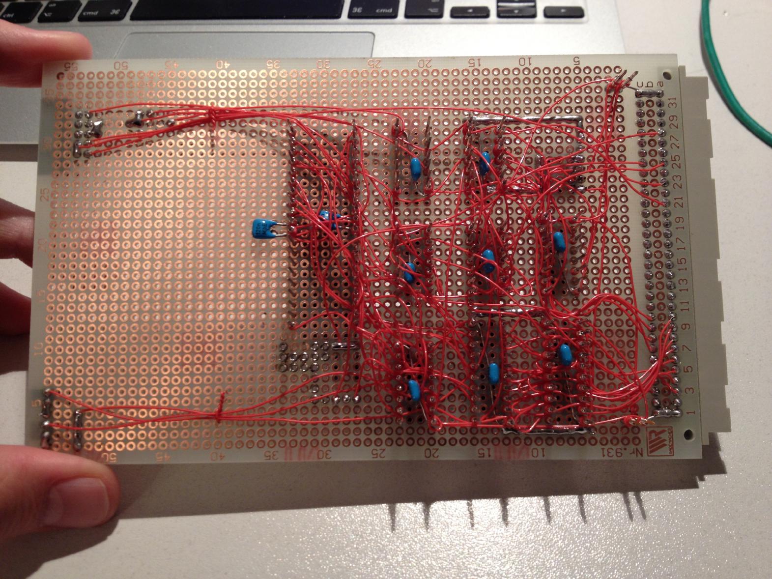
The two pictures below show the completed video controller card: The circuitry occupies about half of an Euro card (160mm times 100mm) (the connector on the lower left in the left picture is the AVR programming adapter). The wiring is done traditionally in wire-wrap technology, my favorite way of building digital circuits. (I am rather desperately looking for wire-wrap sockets as the commercial ones still available are too expensive for my hobby-budget. If you know of any old (cheap) stock, please let me know. :-) ) |
|
|
|
|
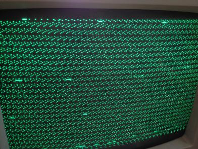
Although the AVR-code was originally suited for an ATmega 32-chip its current version was targeted for an ATmega 328 which has a different layout concerning IO and RAM. Unfortunately all we had at our hands was an ATmega 32-16 chip, so the software had to be ported back to this chip which proved to be more of a challenge than initially expected. Ingo did the initial adaptation, mapping all the IO pins to those required by my hardware design. At first the ATmega 32-16 did not generate any signals at all until we realized that it does no have memory mapped IO but uses explicit in/out instructions. Changing all affected places in the code yielded a first picture as shown on the left. This should have shown a screen full of pipe-symbols "|". Obviously, there was a major timing problem (which I still do not fully understand). A closer examination of the video signal with an oscilloscope showed that the signal part discriminating the horizontal synchronization impulse and the actual video information was excessivly long. Fortunately we were able to track down the related code sequence and changed a loop-counter which, after some fine-tuning, yielded a stable picture. (The part I do not understand is how this part of the code could have worked initially - the value now used is consistent with my rough calculation while the original loop-counter was way too large.) |
|
The picture on the right shows the video signal after adapting this timing loop and changing the two resistor-values combining the synchronization pulse and the video signal from the shifter. And then the problems started... Until this I did not think much about the fact that there were always garbage characters in the second to last line of the display. Now that the video output was stable and looked reasonably well it was time to fix this problem. It took most of a day until I figured out that there still were some places in the code which assumed that the RAM area of the AVR-processor was running from 0x0100 to 0x08ff while that of the ATmega 32-16 used here runs from 0x0060 to 0x085f. I already had changed all constants that I could identify directly in the code by appropriate symbolic names reflecting the memory layout of my AVR-processor. To make a (really) long story short: There were some places in the central video generation routine and in the command interpreter which relied on the memory layout of the ATmega 328 which were not too obvious on first sight. The garbage characters were, as I expected, the memory locations used for the stack. Fixing this problem was a matter of minutes (following the hours of reading code :-) ). |

|
|
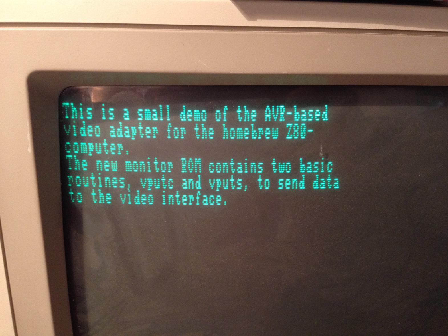
The picture on the left shows the output generated by this video interface - isn't is marvelous (thanks to Daryl's and Grant's software)? Of course, the simple monitor program for the Z80 based computer was extended by adding two system calls vputc and vputs. vputc sends a single character to the video interface while vputs transmits a zero terminated string to the interface. The software for this project can be found here. This ZIP-file contains the complete sources and a small shell script make.bash which I used to build and transfer the software to the AVR-processor. The Z80 monitor system is available upon request (by mail :-) ). |