|
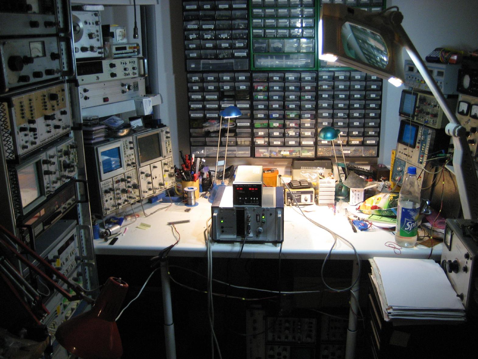
Devices to measure time are incredibly interesting - especially electronic devices (mechanical clocks are - ummm - too mechanical for me, I fear). When I was a child I built some simple digital clocks either based on counting the zero crossings of the power line signal (50 Hz in Germany) or relying on a quartz (one day someone donated a 100 kHz quartz for my clock - at least the quartz has survived, the clock is long since gone, taken apart for parts and lives on in many different incarnations). But even with a good quartz, maybe even a oven stabilized quartz, it is difficult to built a clock with a stability of better than 10 ** -9. So I dreamed about having my own atomic clock for many years, but getting a cesium primary standard is highly unlikely (although there are enthusiasts like Tom Van Baak, one of the Time Nuts, who owns not only multiple cesium clocks but also hydrogen masers!) and even getting a rubidium secondary frequency standard was out of the question. Luckily this has changed - a couple of days ago I found an EFRATOM (now Symmetricom) LPRO-101 rubidium oscillator at a large online auctioning house for a very reasonable price. With this oscillator as the basic building block for a really stable clock I decided to built yet another clock (my last digital clock design was at least 20 years earlier, so this will be a journey into my own childhood :-) ). The picture above shows the clock in its current state - since this is a work in progress this picture will change as the web page will be extended gradually. |
| The rubidium oscillator: | |
|
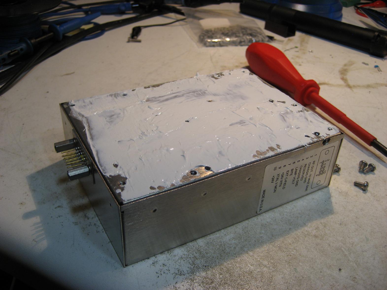
The LRPO-101 rubidium oscillator is a completely self contained unit requiring only minimal external circuitry to be used in a generator/counter/clock circuit. Since the device gets quite hot it is important to mount it onto a heat sink or metal frame to get rid of the excess heat (read the respective section of the manual - for bench use a large heat sink is recommended). Since my clock - at least the oscillator - will be housed in a small 10 inch standard enclosure, I decided to mount the rubidium oscillator on one of its side walls. To ensure a good heat flow from the oscillator to the enclosure I applied quite some heat conductive past (after care- and painfully removing the rather strange and damaged heat conductive sheet that came with the oscillator) as one can see on the right. |
|
|
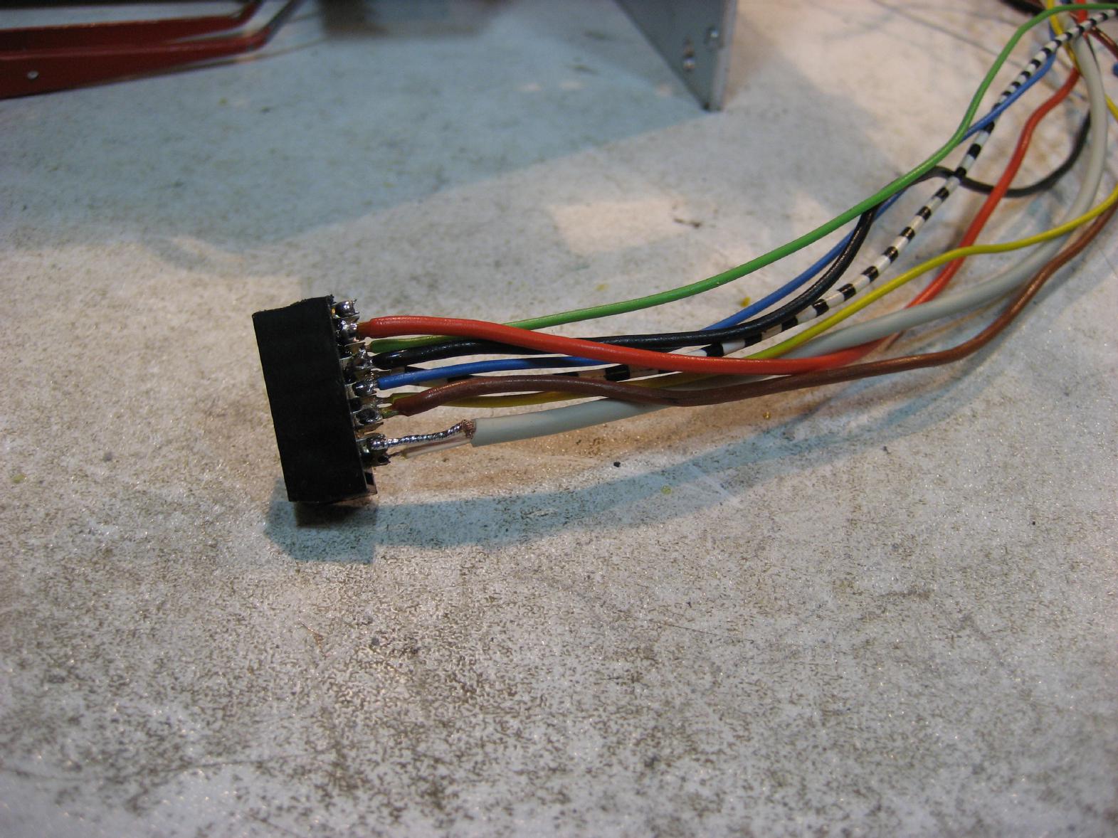
Connecting the LPRO-101 is rather simple - all signals are available at a 10 pin connector (9 of these pins are actually in use). The signals are these:
The picture on the left shows my homebrew connector made from a strip of crimp connector which was left from an old SCSI-cable. |
| The LPRO-Adapter-Module: | |
|
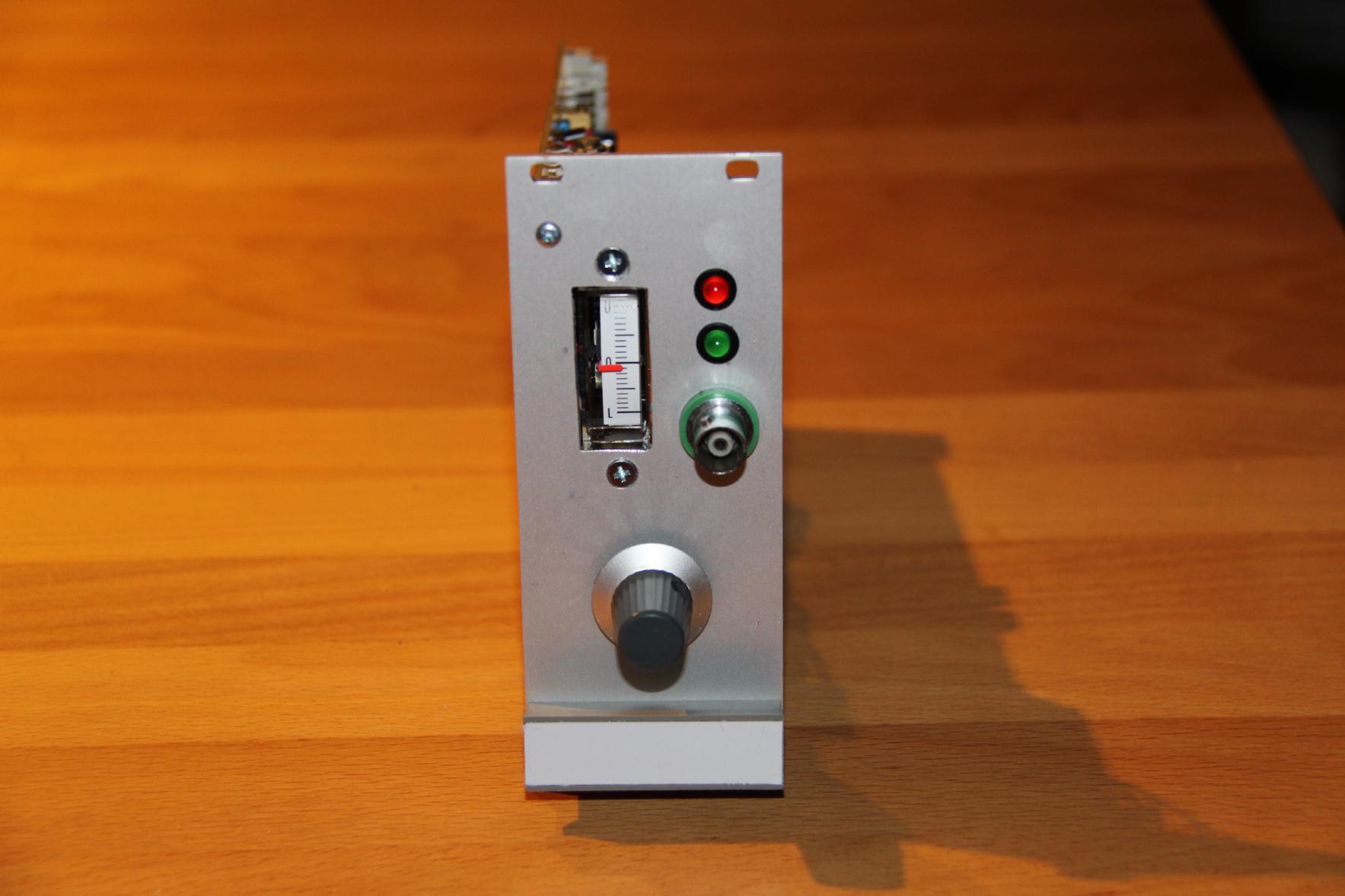
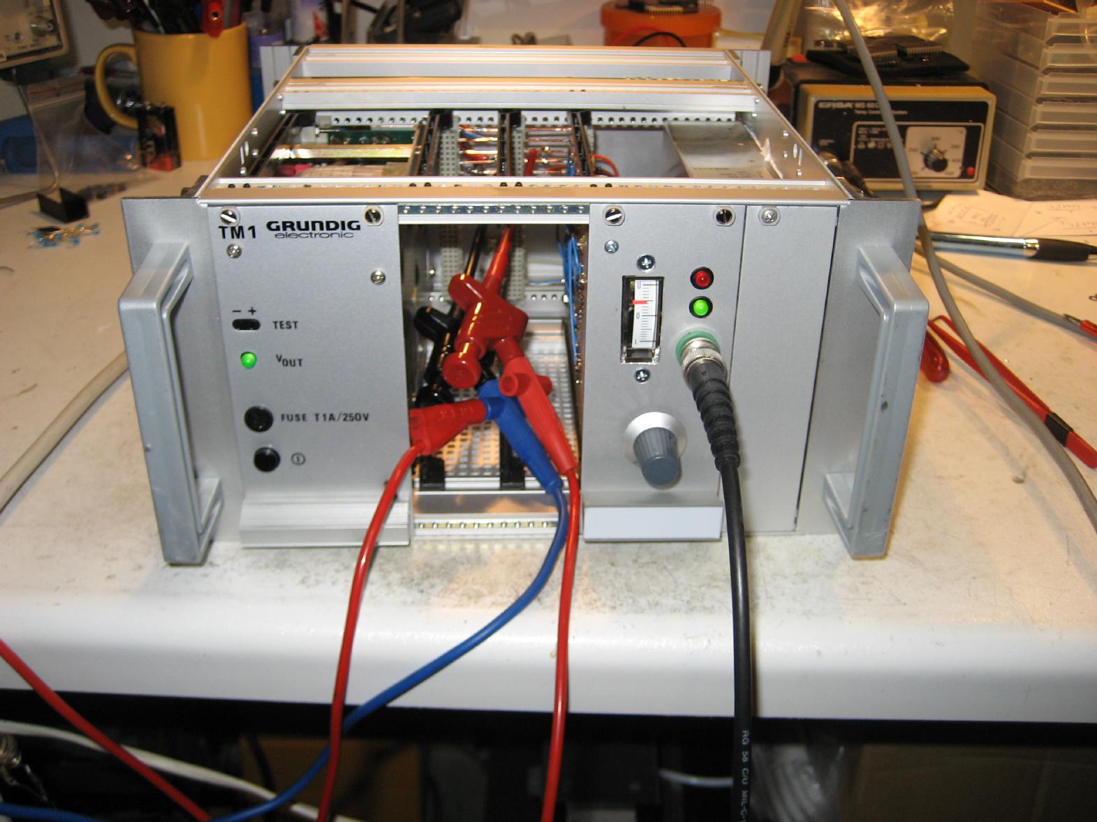
Above I have written that interfacing the LRPO is simple - in a minimal circuit all you will need is +24 V to generate a 10 MHz output signal. Since I have been infected by the way HP built its marvelous test and measurement equipment, this simple approach was not an option for my device. First of all I need some health check instrument to see if all supply voltages are in range. Second, I want sine output of 10 MHz, 5 MHz, 1 MHz and 100 kHz as well as TTL outputs of 10 MHz, 5 MHz, 1 MHz, 100 kHz and 1 PPS. To accomplish this, I will need three modules, each housed on a single Euro card. The first module is the LPRO-Adapter-Module which essentially interfaces with the LPRO rubidium oscillator. The picture on the right shows the front of this module. On the upper left is a small analog instrument which is used to monitor LAMP VOLT, XTAL V MON and the supply voltages of +24V, +12V, -12V and +5V. The source to be monitored can be selected using the knob on the bottom of the module. The two LEDs show the current operating state of the rubidium oscillator (unlocked (red) and locked (green)). |
|
|
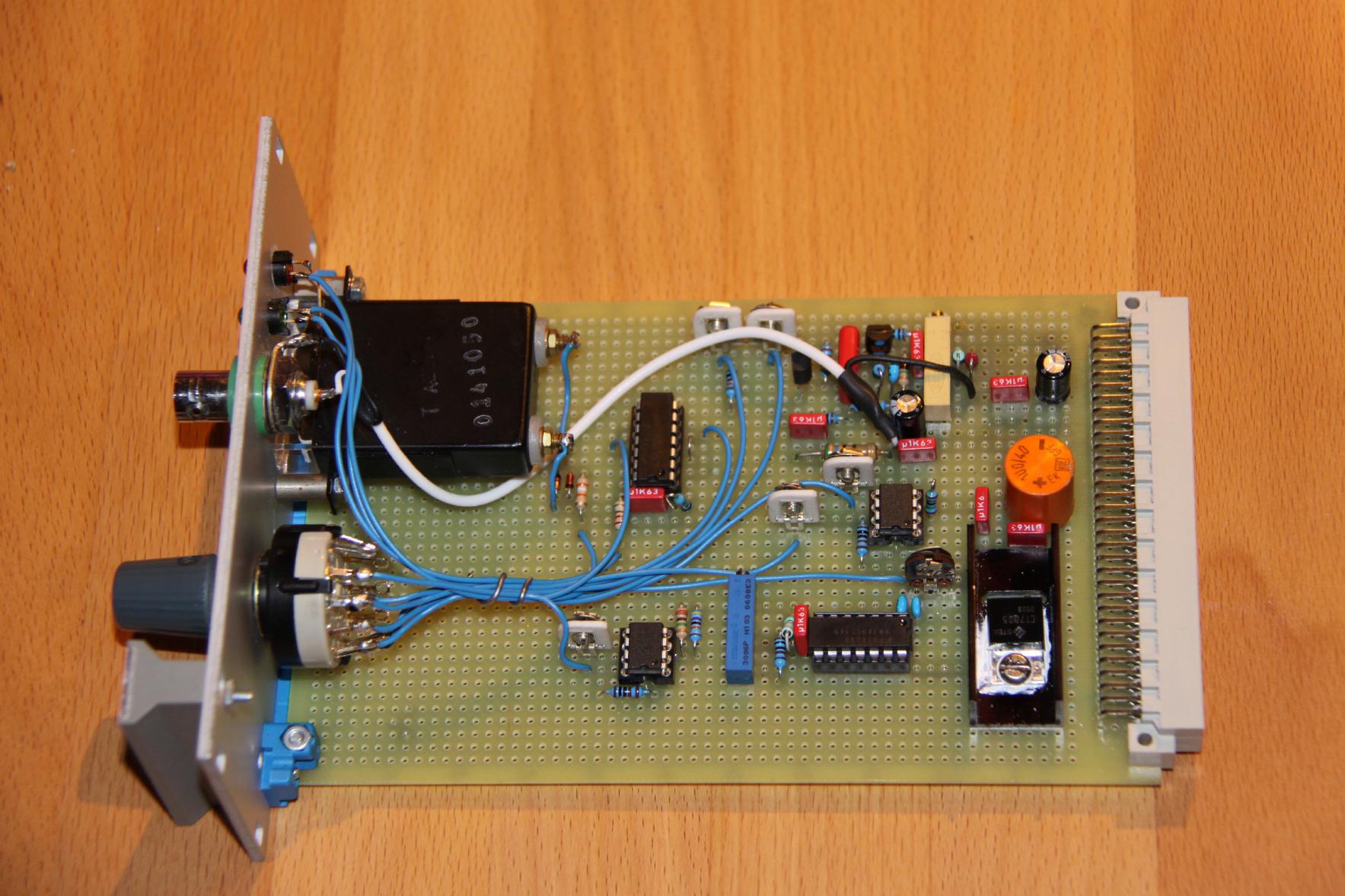
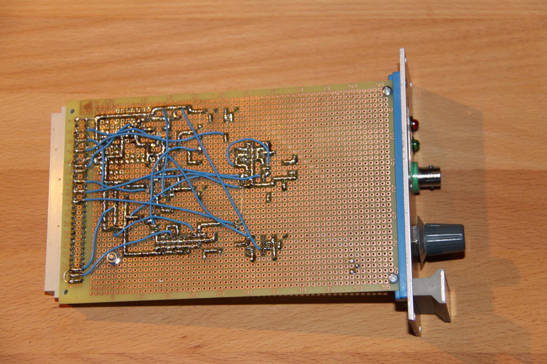
The picture on the left shows the adapter module in more detailt. Since I am really paranoid when it comes to delicate equipment like the LPRO-101 the first thing I built was a buffer amplifier for the 10 MHz output of the LPRO. This amplifier, which has been implemented with discrete parts, can be seen in the upper right part of the board. This amplifier is a two stage amplifier with a FET input stage and a NPN output stage. The signal after the input stage is used to feed a 74HCT14 Schmitt trigger circuit to generate a 10 MHz TTL-like signal for further processing while the output of the second stage is fed to the BNC jack on the front panel of this module. The remaining circuitry is for monitoring the LPRO-module and the power supply of the device. Be careful not to overload the various outputs of the LPRO - even the BITE output has too high an impedance to be fed into standard TTL circuitry, therefore another 74HCT14 has been used here. The signals LAMP VOLT and XTAL V MON are buffered by single operational amplifiers (OPA27). |
|
The picture on the right shows the back of the adapter module. The layout is a bit suboptimal :-) but since I just started soldering without much planning before I had to change the circuitry in some parts several times. The 10 MHz amplifier proved to be a bit tricky and was the part of the circuit I changed most often until I got a really pure output signal (this can be seen below in the pictures of the first test run). Just as a reminder for me - here comes the pin out of the adapter unit:
|
|
|
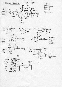
The schematics of the LPRO-101 adapter can be viewed after clicking on the picture to the left. |
| The enclosure: | |
|
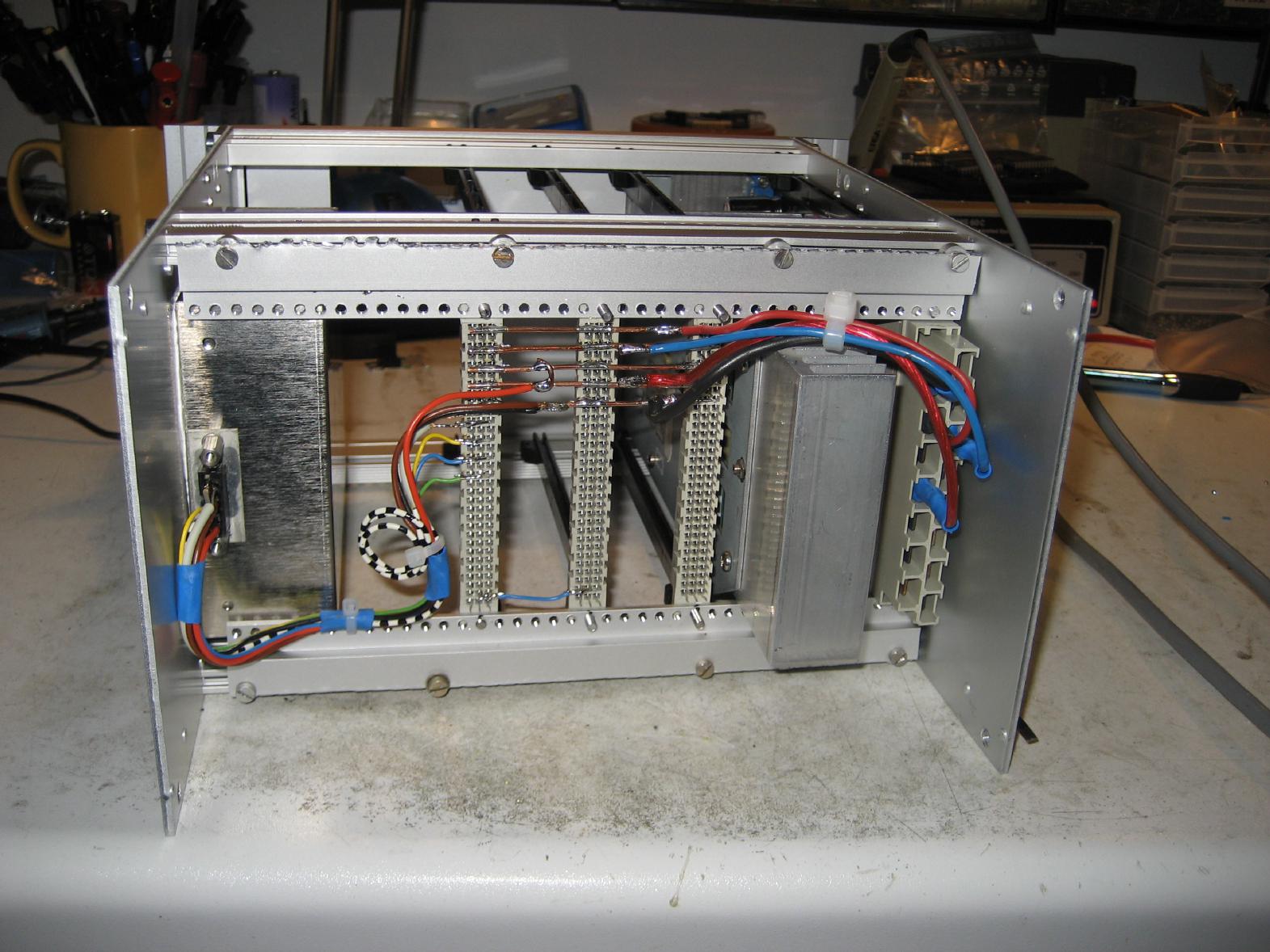
Fitting everything into the 10 inch enclosure made me nuts! I hate (!) these enclosures! Especially when the get delivered with the wrong set of accessories which won't fit without applying significant amounts of sheer force (saw, box column drill etc.). Nevertheless, I somehow made everything fit - the picture on the left shows the backplane of the overall device. On the far left is the LPRO-101 mounted to the wall of the enclosure. The board right next to it will be the adapter module, followed by the (still to be constructed) digital divider board and the (also to be done) sine converter board. On the far right is the power supply - this is a simple supply once made by Grundig that somehow found its way into my well assorted junk box. Its outputs are +12V, -12V and +24V (unregulated but with next to no ripple at all). |
|
The picture on the left shows the back of the overall device - in the middle, next to the power plug, is a BNC jack which will eventually output a 1 MHz sine signal based on the 10 MHz output of the LPRO-101. This 1 MHz signal will then be used (in the near future) to drive my HP 59309A clock. |

|
| 1st test run: | |
|
Believe it or not but the whole contraption worked right out of the box (although I have to admit that I tested the adapter module prior to receiving the LPRO-101 with a HP sine generator to make sure that my 10 MHz amplifier works flawlessly). The picture on the right shows the overall device during the very first test run. The clips were used to monitor the +24V supply line which varied from +24.2 Volts during the initial heating phase to about 26.5 with decreased load after the LRPO-101 reached its operating temperature. The cable with the BNC connector delivered the 10 MHz output signal to my trusted Racal Dana counter and my Marconi spectrum analyzer. When I first switched on the device I was afraid that the LRPO-101 might be a defective unit (the price I paid was considerably lower than any price I have seen previously so I feared that it might be a scrap unit). As it turned out, my LPRO-101 is healthy - its LAMP VOLT output shows a level of a bit more than 7 Volts. |
|
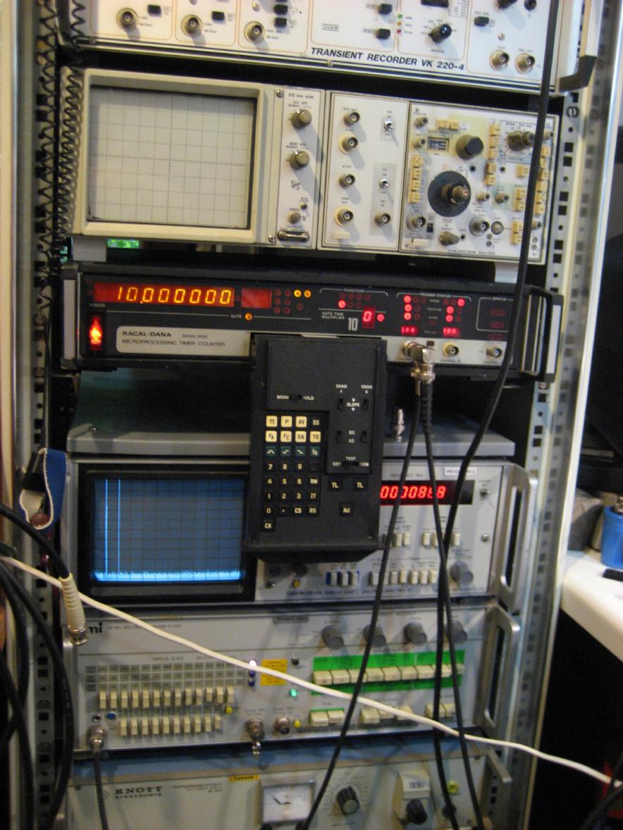
The picture on the right shows my Racal Dana counter and the Marconi spectrum analyzer fed by the 10 MHz output of the adapter module (the counter slowly drifted away after about half an hour and showed a frequency of 10000003 Hz - quite impressive for a device being more than thirty years old by now, isn't it?). I am quite impressed with the behaviour of my 10 MHz buffer amplifier - as one can see on the spectrum analyzer's monitor, its output is very clean - the display covers the frequencies beween 0 Hz and 110 MHz - the large spike on the left is the 0 Hz mark with the 10 MHz output signal of the amplifier right next to it. The next step will be to build the digital divider module which I will do the traditional way using many 74LS90, 74LS74, 74AC04 etc. This module will deliver 10 MHz, 5 MHz, 1 MHz, 100 kHz and 1 PPS outputs on its front plate. After that the three channel sine converter module will be built which will generate 5 MHz, 1 MHz and 100 kHz output signals. |
|
| The digital divider module: | |
|
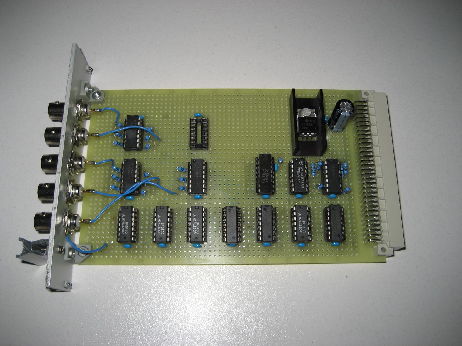
Today (11-JUL-2010) I reached my next mile stone - I completed the digital divider board which generates outputs of 10 MHz, 5 MHz, 1 MHz, 100 kHz and 1 PPS - each with TTL level. The picture on the left shows the overall divider module: The lower row of chips consists of seven 74LS90 divider circuits yielding a 1 Hz signal at the left side. The middle row contains (from left to right) two 74AC04 (these are used as output drivers), a 74LS123 (this monoflop is used to generate a proper 1 PPS pulse), a 74LS74 (used to derive the 5 MHz signal) and yet another 74AC04 (to drive the output lines on the back panel). The upper row contains a single 74AC04, an empty socket (I used this socket to test the card without the rubidium oscillator - just fit a 10 MHz TTL oscillator in the empty slot) and a simple 5V regulator. |
|
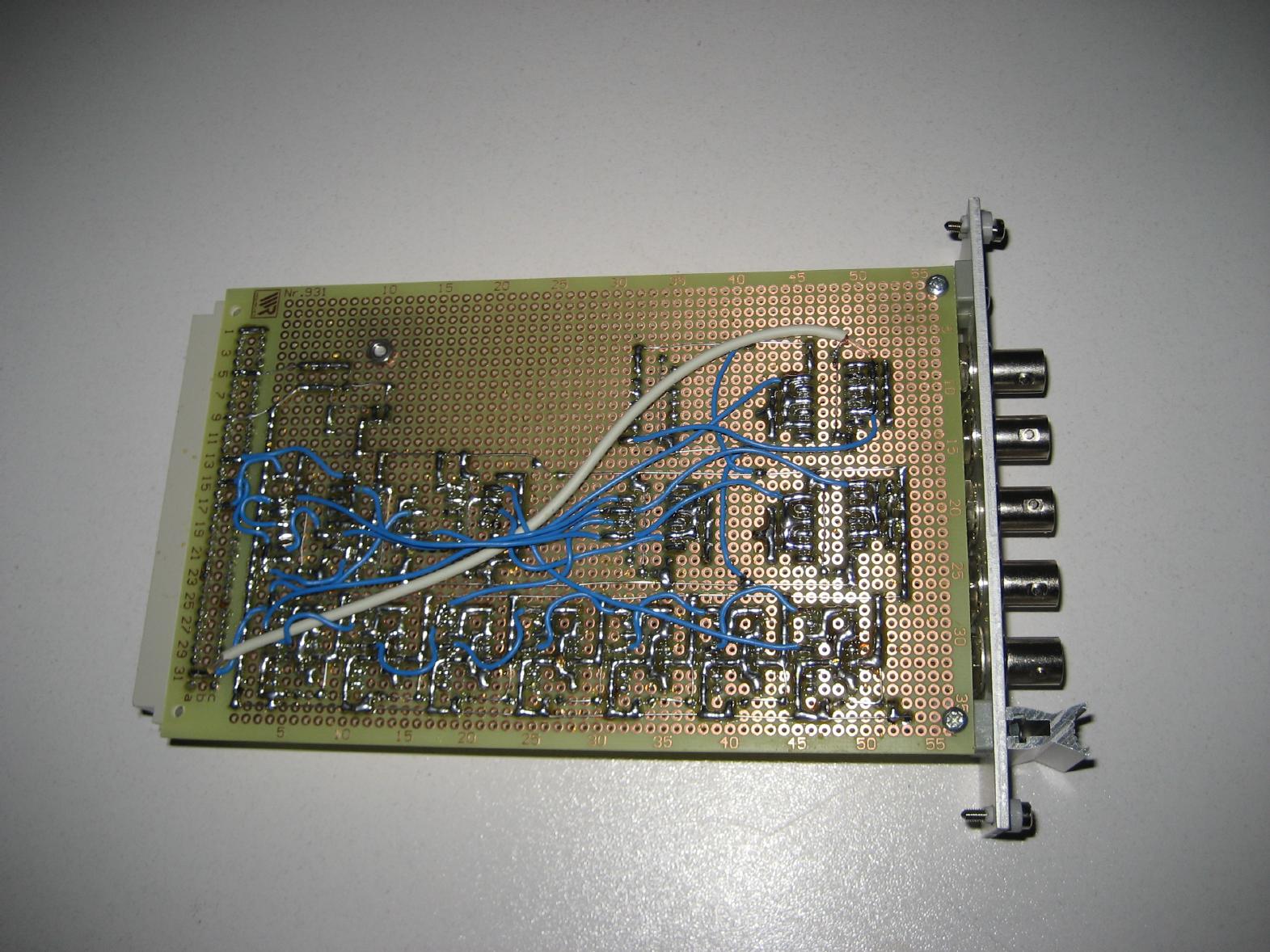
The picture on the right shows the solder side of the divider module - this was horrible to build due to the high amount of connected pins of the seven 74LS90 and other chips (it is more fun to build analog circuits than digital ones :-) ). On the right are the five BNC jacks delivering the various output signals - each buffered by triple 74AC04 gates with 51 Ohm resistors in series. |
|

|
The schematics of this simple digital divider (which, as I was told a couple of minutes ago, will introduce way too much jitter to do any precision measurements with it) can be viewed after clicking on picture to the left. |
| Rubidium atomic clock: | |
|
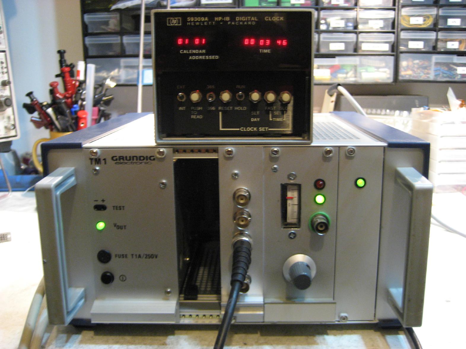
With the digital divider board, the first milestone of my homebrew rubidium oscillator based clock has been met. The picture on the left shows the overall setup consisting of the oscillator and a HP 59309A clock sitting on top of it (isn't my home laboratory cozy? :-) ). That's it! I have my own "atomic" clock - sort of. :-) The next steps will be to design and build the sine converter module and a highly sensitive phase comparator to compare my clock's performance to other devices. |
| Updates: | |
|
Following some advice I got from participants of the Time Nuts mailing list (thank you all very much for the constructive crisicism! :-) ), I added a quad D-flip flop to the digital divider module to buffer the 5 Mhz, 1 MHz, 100 kHz and 1 PPS outputs. All four flip flops are fed with the raw 10 MHz output signal from the Rubidium oscillator as clock input. This assures minimum phase jitter. Since this is a very simple and cheap solution it is far from being perfect. It might be possible that the divider chain, consisting of quite a lot of 74LS90 chips, might show enough temperatur drift that an output signal like the 100 kHz or especially the 1 PPS signal will "miss" the 10 MHz clock used to trigger the aforementioned quad D-flip flops. This would, indeed, make the phase jitter problem even worse since the jitter would now be quantized in 100 ns steps. Nevertheless first tests have not shown this problem, so I am quite happy with this simple solution. |