Restoring a PDP 11/34


Restoring a PDP 11/34
Since I am a bit paranoid, I would not just power on such a machine and test my luck - chances are good that something will be fried or die another electronic death.
So first of all, I removed all cards and installed an artificial load for the +5 V, +15 V and -15 V lines to check the switching power supplies. The first thing I noted was that the big relay in the power controller made a terribly humming noise which it shouldn’t do. In addition to that the fuse in the house triggered about every second attempt to switch on the system.
First power on...
A couple of weeks ago I swapped some DEC SCSI disk drives for a PDP 11/34 - it turned out to be a real win-win-situation (normally I hate terms like this but here it is true): My friend was happy about the SCSI drives and a matching desktop enclosure and I am as happy as can be about a wonderful 11/34.
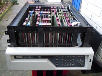
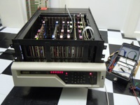
The picture on the left shows the system after unloading it from the car - it is quite well equipped with DL11 boards (of nearly all types, some even third party), has a RL11 controller and - best of all: It has the cache board! My first 11/34 with the optional cache board!
In the following the restoration process of the machine is described - have fun and may the PDP 11 live forever! :-)
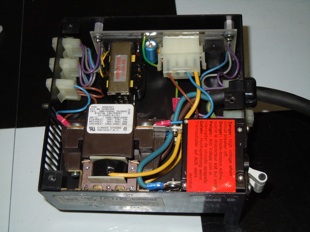
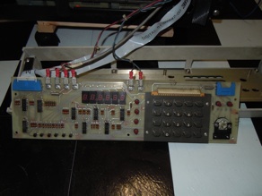
The picture above right shows the power controller - it consists of a small power supply that powers a solid state relay when the front panel switch is turned on. This solid state relay in turn switches on the main relay that applies power to the big main transformer. The problem was that the filter capacitor of this small power supply had lost its capacity, thus the solid state relay was driven by a rather unfiltered voltage which in turn caused the solid state relay to switch the main relay on and off with 50 Hz. Since the main relay has quite an inertia it won’t open completely but generate an annoying hum. Replacing this capacitor cured the problem.
Since all power supply voltages measured OK, I decided to give the machine a first try: Just the two CPU cards (control and data path), the KY11-LB, the bootstrap card and grant continuity cards in all other slots.
The machine powered up and I was able to enter the simplest possible test program into memory (load an even address with 000777 which is a relative branch to the very same location i.e. a tight loop) and run it. Nevertheless the console behaved quite erratic at times. A couple of minutes later the machine stopped working. The console displayed garbage and was non-responsive to any keys pressed.
Rechecking the voltages showed that +15 V and -15 V were now missing, so something obviously had failed...
Since the -15 V supply relies on the +15 V supply for proper operating, I attributed this missing voltage to the missing +15 V and concentrated on the +15 V supply which is located above the power controller.
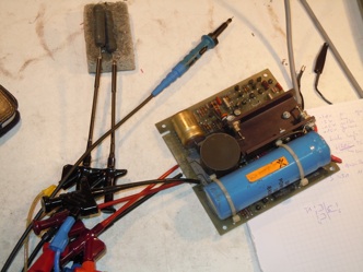
The picture on the left shows this power supply: The neat thing about old DEC switching power supplies is that they are powered by a low voltage (about 25 V AC) which is derived from a big main transformer. Although this makes these power supplies quite heavy, it makes repairing them quite easy since there is no need to worry about lethal voltage in the switching power supplies.
The power supply here is hooked up for a bench test - note the two big resistors on the upper left as artificial load.
It turned out that the switching transistor was always “on”, thus the output voltage of the supply (nearly) reached the voltage present at its input which is much more than +15 V. This in turn triggered the crowbar circuit (thank the DEC designers for this feature that saved the machine!) which in turn burned the 5A input fuse.
The circuit is quite simple and built around a 723 as a controller chip. It turned out that the 723 itself was defective - its reference voltage section was dead. Replacing the chip was quite difficult since it is partially buried under the massive heat sink. Nevertheless, with a new 723 the power supply worked again.
With only the KY11-LB and the bootstrap in the backplane (and lots of grant cards, of course), all voltages were checked again and found to be in range.
Now the next problem the erratic console which was completely dead by now. Careful examination of the ribbon cable connecting the KY11-LB with the front panel showed that it has cracked at one place - guess where: The +5 V voltage was missing on the front panel.
Unfortunately replacing the cable did not cure the front panel problem. The simplest fault was a dark DC ON-LED which turned out to be defective (the first defective LED I ever encountered). This was easy to fix... :-) But why didn’t the console react to any key presses at all?
After some fruitless approaches to debug the KY11-LB which were complicated by the fact that I do not have an extender board, I decided to see if I had another KY11-LB to swap in - just to make sure if the problem was on the front panel or the KY11-LB itself.
It turned out that the KY11-LB had failed (as a result of the +/-15 V supply failure?).
That was bad news but since I had a spare (the only one), I decided to use the spare and postpone debugging of the original KY11-LB until later.
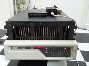
The picture below shows the machine running (again) fine with the repaired power controller, repaired +15 V switching power supply, replaced DC ON-LED, replaced ribbon cable and replaced KY11-LB.
After this I drilled a small strip of metal to replace the missing cable retainer on the back side of the machine, reinsert the FPU and cache cards and add a disk controller. (I would like to cordially thank the person who gave me a CMD UNIBUS-SCSI-controller as a present!)
On the left the machine in its (currently) final configuration can be seen: A PDP 11/34 with:
FPU, cache, 128 kW MOS memory, DL-11W (SLU & LTC) and CMD 720.
It boots happily RT11XM from the SCSI disk sitting on top of the CPU-enclosure (by the way: This is my first SCSI disk ever - I bought it in the 1990s for a fortune and it has 40 MB capacity! :-) ).
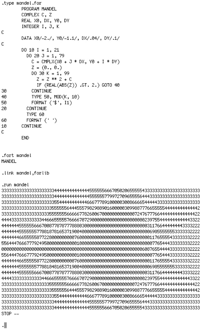
The picture above shows the terminal output of the first session on the machine (with a prepared RT11 disk). A short FORTRAN IV-program that computes a Mandelbrot set is compiled, linked and run.
It’s alive! :-)