| Introduction | ||||||||||||||||||||||||||||||||||||||||||||||||||||
|
The NICE processor is a simple yet quite powerful 32 bit processor for educational purposes. The acronym stands for "NICE Is Charmingly Elegant" which is not too presumptuous considering its lean architecture. |
||||||||||||||||||||||||||||||||||||||||||||||||||||
|
NICE employs a rather simple instruction (quite RISC like) combined with powerful addressing modes (a more CISC like feature), to simplifying programming. The instruction set is fully orthogonal, i.e. all instructions can be combined with all addressing modes, so it is possible to access values stored in memory as well as register contents in a single instruction, etc. NICE has sixteen general purpose registers, R0,R1,...,R15. General purpose means that no register is special in a way that forbids certain operations on it. Nevertheless some registers serve special functions - R15, for example, is the program counter, R14 is the status register, etc. Since all addressing modes and all instructions can be combined with all registers few instructions are sufficient to perform all necessary instructions for a general purpose computer. So it is, for example, not necessary to provide jump or branch instructions since the program counter, R15, can be easily modified using arithmetic operations like MOVE, ADD, etc. |
|
|||||||||||||||||||||||||||||||||||||||||||||||||||
| The status register | ||||||||||||||||||||||||||||||||||||||||||||||||||||
|
The picture below shows the overall structure of the status register R14 - the upper eight bits are status bits which may be (mostly) modified by arithmetic or shift instructions. The lower 24 bits contain the address of the interrupt vector control structure in memory.
|
||||||||||||||||||||||||||||||||||||||||||||||||||||
|
The table on the left describes the eight status bits of the status register - the two uppermost of these bits will be described later when dealing with interrupts. Nearly every instruction has a flag to control whether it may update the contents of the status register or not. This has the advantage that the status bits will be left unchanged if desired thus eliminating the need for many backup copies of the status register contents. Bit 23 of R14 contains the fixed value 1 which is essential for unconditional execution of instructions as described below. | |||||||||||||||||||||||||||||||||||||||||||||||||||
| The instruction format | ||||||||||||||||||||||||||||||||||||||||||||||||||||
|
NICE employs a very simple fixed instruction format to simplify instruction decoding. This format is shown in the following table
The first part of an instruction, the condition code contains information to allow the conditional execution of the instruction depending on the status of certain status bits. The next part, the opcode, controls which instruction is to be executed. All instructions are grouped into three groups: ALU instructions (arithmetic/logic), shift instructions and miscellaneous instructions. The next three fields, destination, source 0 and source 1 contain the necessary information to access both input and the output operand of the instructions. |
||||||||||||||||||||||||||||||||||||||||||||||||||||
| Conditional execution | ||||||||||||||||||||||||||||||||||||||||||||||||||||
|
The condition field of each instruction consists of four bits divided into two groups as shown on the right. |
|
|||||||||||||||||||||||||||||||||||||||||||||||||||
|
The three bits (30..28) of the condition field are used to select one of the eight upper most bits of the status register R14. If these bits are, for example, 000, the 1 bit of R14 is selected. A select code of 100 would therefore select the N bit, etc. If bit 31 of the condition field is set, the value of the selected status bit will be negated (without changing it in the status register). Thus the condition code 1011 would select the Z bit, negate it and execute the instruction only if the result of this operation is 1. The assembler notation of a condition field looks, for example, like ?!N - this would result in the N bit being selected and negated (by using the exclamation mark). The leading question mark denotes the specification of a condition field. Consequently, each instruction to be executed unconditionally would have to be preceeded by the condition code ?1 to select the 1 bit of the status register. To facilitate programming, the assembler (see below) will automatically create appropriate condition field bits if ?1 is omitted to make every instruction without an explicitly specified condition code an unconditional instruction. |
||||||||||||||||||||||||||||||||||||||||||||||||||||
| ALU instructions | ||||||||||||||||||||||||||||||||||||||||||||||||||||
|
The format of an arithmetic/logic instruction is shown in the table above. The zero bit in position 27 of the instruction word denotes an ALU instruction (if this bit is set to one the instruction might be a shift or halt instruction). If bit 26 (the C bit) is set, the instruction will use the content of the C (carry) bit of the status register as an additional addend of the current operation thus allowing multi precision arithmetic. Bit 27 (the M bit) controls if the current instruction may modify the status bits of R14. If set, the V, N, Z, C and X bits will be set accordingly to the result of the instruction. |
|||||||||||||||||||||||||||||||||||||||||||||||||||
|
The table on the left shows all available ALU instructions of NICE. (Not all of them are equally useful - some were the by products of the ALU chips used in NICE's predecessor, but this is a long story.) The four bits shown in the opcode column correspond to bits 24 to 21 of the ALU instruction, so 16 different ALU instructions are possible. The description column makes use of some special symbols to denote operations: An exclamation mark stands for bit wise negation, || and && represent bitwise or and and operations, ^ denotes a bitwise exclusive or operation. All in all the most frequently used operations will be MOVE, ADD, AND and OR (it should be noted that some of the remaining instructions permit quite funny tricks as shown in the book "Hacker's delight"). |
|||||||||||||||||||||||||||||||||||||||||||||||||||
| Shift instructions | ||||||||||||||||||||||||||||||||||||||||||||||||||||
The table above shows the format of a NICE shift instruction - it is identified by bit 27 which is set to one. To distinguish a shift instruction from a halt instruction, bit 26 is used - if it is cleared (as shown), the instruction is a shift instruction. Bit 25, the M bit, has the same purpose as in an ALU instruction - the contents of the status register (apart from the carry bit which may be modified by some shift instructions regardless of the state of bit 25) may be modified only if this bit is set to one. |
||||||||||||||||||||||||||||||||||||||||||||||||||||
|
The table on the right shows the sixteen different shift instructions available in the NICE processor. The four opcode bits correspond to bits 24..21 of the shift instruction (like in an ALU instruction). The shift direction is denoted by ">" or "<" accordingly. The optional characters left and right to the direction character denote the source and destination bit of the shift operation. The instruction 0<0, for example, shifts to the left, fills the word from right with zero and discards the bits shifed out. Accordingly, C>C performs a right shift - the word is filled from the left with the content of the C bit of the status register while the bit shifted out on the right is written into the C bit (so this instruction is a 33 bit rotation through the carry bit). |
|
|||||||||||||||||||||||||||||||||||||||||||||||||||
| The HALT instruction | ||||||||||||||||||||||||||||||||||||||||||||||||||||
The format of a HALT instruction is shown in the table above. It is distinguished from ALU and shift instructions by having both bits 27 and 26 set to one. The remaining bits of this instruction have no meaning and should be zero. If a HALT instruction is encountered by the processor and if it is executed (controlled by the condition field) it will instantaneously stop all processor activities. |
||||||||||||||||||||||||||||||||||||||||||||||||||||
| Coding source and destination operands | ||||||||||||||||||||||||||||||||||||||||||||||||||||
|
All NICE instructions are (in principle) able to operate on three operands: Two source operands (if applicable) and one destination operand (the HALT instruction does not use either operand type). As may be seen in the instruction format, each operand is specified using a seven bit field which is (more or less) interpreted the same way for either source or destination operands. The seven bits of an operand field are divided into a three bit mode field and a four bit register number to select one out of the sixteen NICE registers as an operand. The table on the left shows the eight possible addressing modes for each operand. Rxx denotes register number xx (the register number is contained in the lower four bits of the operand field). |
||||||||||||||||||||||||||||||||||||||||||||||||||||
|
"++" and "--" denote pre- or postincrement/-decrement operations. Rxx++ as a destination operand will write the result of the current instruction into Rxx and increment Rxx afterwards. The @ sign denotes relative addressing. For example, @Rxx as source operand will load the contents of the memory address which is contained in Rxx. The # sign denotes a constant (see below). |
|||||||||||||||||||||||||||||||||||||||||||||||||||
|
Take the instruction "ADD R3, R2, R1" as a simple example - this will add the contents of the registers R1 and R2 and write the result into register R1. A more complicated example is "ADD @R3, @R2, @R1" which will add the contents of the main memory locations pointed to by the contents of R2 and R1 and write the result into the memory cell which address is contained in R3. The instruction "ADD R3, R2, #0x12345678" will add the constant 0x12345678 to the contents of register R2 and write the result into R3. Using the increment/decrement modes, even complicated instructions like "ADD @R3++, --R2, @#0x12345678[R1]" are possible. This instruction will:
If an operand needs constants, these values will occupy the memory locations following the instruction itself. An instruction employing three constants will occupy four 32 bit memory locations - one for the instruction and three for the constants being used. |
||||||||||||||||||||||||||||||||||||||||||||||||||||
| A coded example instruction | ||||||||||||||||||||||||||||||||||||||||||||||||||||
|
The following paragraphs will show how the example instruction
?!Z ADD[M] @R3++, --R2, @#0x12345678[R1]
Since "ADD" is an ALU instruction, bit 27 of the instruction has to be zero. The C and M bits (bits 26 and 25) will be zero and one respectively since the M bit is set explicitly by "[M]". The "ADD" instruction has the opcode 0011, so bits 24 to 21 are now known, too. The destination operand of the above instruction is "@R3++" - this corresponds to mode 110 and 0011 as the register number so the destination operand field will be 1100011. Accordingly the first source operand, "--R2", translates to 0010010 while the second source operand, "@#0x12345678[R1]" has mode 111 and register number 0001. The constant "0x12345678" will be placed into the memory location directly following the instruction. Taking all of these bits together, the resulting instruction looks like:
         10110010011110001100100101110001
         00010010001101000101011001111000
| ||||||||||||||||||||||||||||||||||||||||||||||||||||
| Example programs | ||||||||||||||||||||||||||||||||||||||||||||||||||||
|
The following sections show some more or less simple example programs demonstrating most of the instructions, addressing modes and overall capabilities of the NICE processor. The examples will show the notation of NICE assembler programs as well. |
||||||||||||||||||||||||||||||||||||||||||||||||||||
|
Summing: The program on the right will calculate the sum of all numbers from 1 to 0x1000. Register R1 is used as the summing register, R2 contains the value to be summed which will be decremented during each loop. If the result of decrementing R2 is zero, the condition "?!Z" of the MOVE statement (which in fact is a simple conditional jump to the label LOOP) will be false. This causes the MOVE instruction to be skipped and the HALT instruction to be executed. |
         .ORG   0         ; Set base address
I        .EQU   0x1000    ; Define constant
         MOVE   R14, R0   ; Clear status reg.
         MOVE   R1, R0    ; Clear summing reg.
         MOVE   R2, I     ; Set R2 to I
LOOP     ADD    R1, R1, R2; R1 := R1 + R2
         DEC[M] R2, R2    ; R2 := R2 - 1
     ?!Z MOVE   R15, LOOP ; Zero reached?
         HALT             ; Yes -> HALT
|
|||||||||||||||||||||||||||||||||||||||||||||||||||
DEST      .EQU   0x15          ; Destination
PC        .EQU   15
          .ORG   0             ; Start addr.
START     MOVE   R2, DEST
          MOVE   R1, START
          MOVE   R3, END
LOOP      MOVE   @R2++, @R1++  ; Copy word
          XOR[M] R0, R1, R3    ; Finished?
      ?!Z MOVE   PC, LOOP      ; No -> Loop
END       HALT                 ; Yes -> HALT
|
A self replicating program: The program on the left replicates itself in NICE memory. It copies the entire memory area enclosed by the START and END labels. The constant DEST contains the destination start address. To determine if the program has finished its run, the contents of R1 and R3 are compared for being equal. This is accomplished applying a bitwise exclusive or on the contents of R3 and R1. Since the result is not of interest itself it is discarded by writing into R0 which is always zero. If both contents are equal the result is zero which will result in the Z bit of R14 being set. |
|||||||||||||||||||||||||||||||||||||||||||||||||||
| The NICE emulator | ||||||||||||||||||||||||||||||||||||||||||||||||||||
|
While developing NICE and its predecessor, u-EP-1 (which resulted even in a partially working hardware implementation), two more or less rudimentary emulators were written to allow studying the processor architecture, its features and drawbacks. These emulators were written in VAX-Fortran and VAX-C respectively, but both lacked a suitable user interface - the Fortran written emulator featured a batch interface reading command files and writing result files, the C program had a command line interface. During 2004 a friend of mine, Thomas Kratz, wrote a wonderful NICE emulator using Perl and Tk for the GUI (which in fact led to a very short lightning talk at the YAPC-2004 in Belfast). |
||||||||||||||||||||||||||||||||||||||||||||||||||||

|
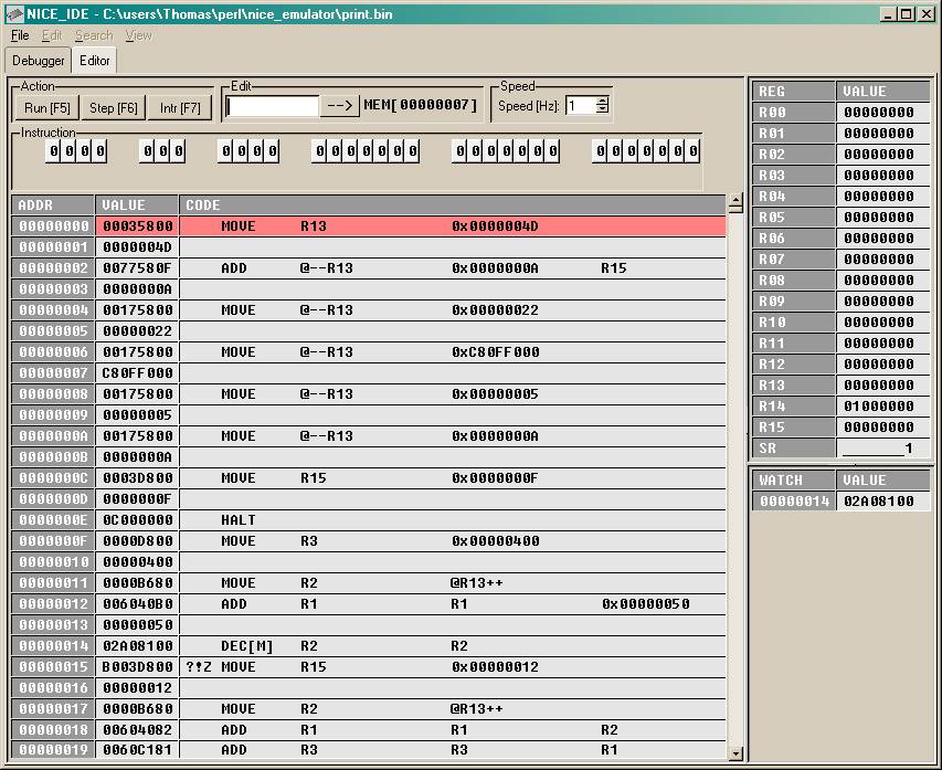
The NICE emulator is in fact a complete development environment containing an editor, an assembler, a debugger and the emulator itself and is thus called NICE-ide (integrated development environment). The picture on the left (you may view an enlarged version by clicking on it) shows the editor window of the NICE-ide with an assembler program visible in the display. Pressing the function key F2 will start the assembler which will write its output in case any errors will be encountered during the run in the white output area at the bottom. Pressing F4 will assemble the program, too, but will write the resulting binary file to disk and switch to the emulator (debugger) window with the current code loaded into memory. |
|||||||||||||||||||||||||||||||||||||||||||||||||||
|
The debugger window is shown on the right - it is divided into five main parts:
|
|
|||||||||||||||||||||||||||||||||||||||||||||||||||
|
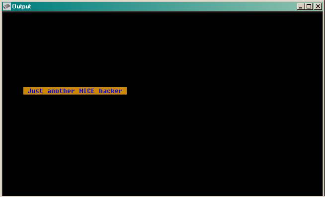
A section of the emulated main memory is mapped to a simple character cell screen which is shown on the left. Writing into one of the display memory cells results in an appropriate character being displayed. The program which produced the output shown left may be obtained in the download section below (written by Thomas, too :-) ). |
|||||||||||||||||||||||||||||||||||||||||||||||||||
| Downloads | ||||||||||||||||||||||||||||||||||||||||||||||||||||
|
||||||||||||||||||||||||||||||||||||||||||||||||||||