|
|
|
Converting a DECserver 200 into a MIDIserver 200
|
|---|
|
For many years I thought about connecting MIDI equipment
like an expander or something like this to one of my VAX
machines running VMS. If you think that using a PC would
be much more simpler, you are right, but using a VAX
running VMS is much more fun! And - it is a system I am
familiar with and I like to program - there is nothing
like QIOs. :-)
|
|
|
|
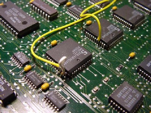
The original clock signal can be obtained from a 74F37 in the right corner of the main board (RS-232 connectors facing to you): |
|
|
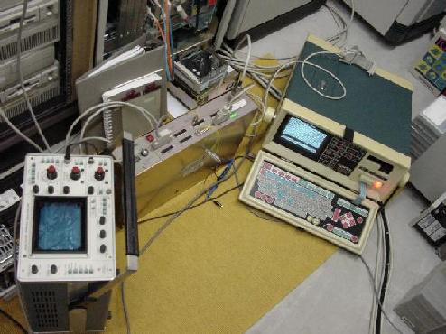
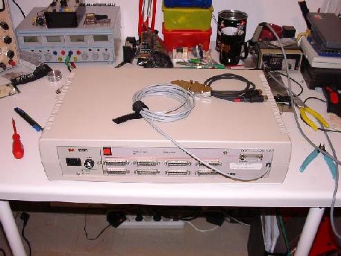
| When I connected DUARTs two, three and four to a 6 MHz crystal clock generator and switched the DECserver 200 on for the first time I realized that it did not pass its self test routines. It identified ports three to eight as buggy and disabled them. Another test with a simple switch was more successful. During startup all DUARTs received the same (original) clock signal so the DECserver 200 passed its self test without problems. After completion of the test routines I flipped the switch so the DUARTs (except DUART one) received the new 6 MHz clock signal. Sending a text from a VMS machine via LAT to one of the ports connected to one of these DUARTs showed that the transmission worked flawlessly (despite the overclocking). The following picture shows the test environment of the device. On the left is an oszilloscope to monitor the clock lines, in the middle the modified DECserver 200 can be seen and on the right is an INTERVIEW 4500 serial line analyzer. |
|
|
| The remaining problem was how to get rid of the clock switch since it is not very comfortable being forced to flip a switch each time the device is powered up just to get it through its self test. The trick is to use the signal driving the LED D2 (the self-test-complete-LED) to control a 1-out-of-2 selector (74LS158) to select the original clock signal during self test (LED is off) and to automatically switch over to the new 6 MHz clock signal after the self test finished (LED on). |
|
|
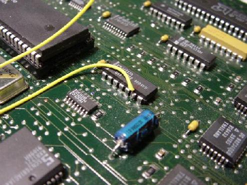
| This small circuit worked very fine so the last thing to do was building a small current loop converter for one of the ports supporting 31250 baud. This driver consists of a 74LS14 as main driver circuit and an opto coupler for decoupling the MIDI input signal from signal and ground of the DECserver 200. The opto coupler can be seen in the lower middle of the picture below: |
|
|
| The following picture shows the MIDIserver 200 after completion. Note the MIDI cable leaving the case on the right - it ends in an 15 pin SUB-D plug. From there MIDI devices are connected via an adapter cable. On the left, next to the AUI-plug, the MIDI/NORMAL switch can be seen which is used to select between MIDI mode (MUX enabled) and normal operation as a simple DECserver 200. |
|
|
|
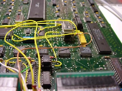
The following picture shows all changes made to the DECserver 200 during the conversion: |
|
|
|
And a simple program to play a few notes via the MIDIserver 200 (this was, infact, my very first test program :-) ): |
#include<STDIO.H>
#include<STDLIB.H>
#include<MATH.H>
#define MIDI_DEVICE "LTA44:"

#define ON 1
#define OFF !ON

#define OK 0
#define ILLCHNL -1
#define ILLNOTE -2
#define ILLVELO -3
#define ILLSTAT -4

int switch_note (FILE **, int, int, int, int);

int main ()
{
    int note, akkord [8] = {50, 54, 57, 62, 66, 69, 74, 78};
    FILE *output_handle;

    if (!(output_handle = fopen (MIDI_DEVICE, "w")))
    {
        fprintf (stderr, "Unable to open device %s.\n", MIDI_DEVICE);
        return -1;
    }

    for (note = 0; note < 8; note++)
    {
        switch_note (&output_handle, 0, akkord [note], 10, ON);
        sleep (1);
    }

    for (note = 7; note >= 0; note--)
    {
        switch_note (&output_handle, 0, akkord [note], 10, OFF);
        sleep (1);
    }

    fclose (output_handle);

    return OK;
}

int switch_note (FILE **handle, int channel, int note, int velocity, int state)
{
    if (channel < 0 || channel > 15)
        return ILLCHNL;

    if (note < 0 || note > 127)
        return ILLNOTE;

    if (velocity < 0 || velocity > 127)
        return ILLVELO;

    if (state == ON)
        fprintf (*handle, "%c%c%c", 144 + channel, note, velocity);
    else if (state == OFF)
        fprintf (*handle, "%c%c%c", 128 + channel, note, velocity);
    else
        return ILLSTAT;

    return OK;
}
|