|
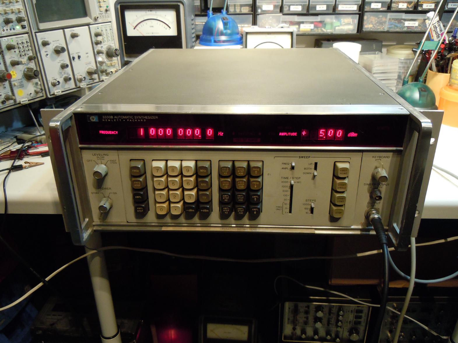
About two years ago I bought a defective HP3330B automatic synthesizer for about 100 EUR with the rationale that I could need some spares for my other HP3330B which is serving me perfectly well since several years. Given the many special HP chips etc. in this device, I thought it would a clever idea to buy a second one to have spare parts, just in case. Then came the day when this second HP3330B sitting on its shelf was literally staring at me and whispering "Repair me, repair me!". Why not? I had nothing to loose, I thought - and since it was a weekend and I had some spare time, I decided to give it a try. Had I known what was to come, I might have never started to repair this device. But now I am glad that I did. :-) |
| Repairing the device: | |
|
After an initial visual check (any obviously broken parts like capacitors etc., input voltage selector set correctly etc.) I turned on the instrument (slowly increasing the input voltage using a variac and carefully looking at the current drawn). Nothing bad happened - no "pooof" sounds or the like, no excessive current but also no display, nothing. So it was time to check the supply voltages. All voltages turned out to be in the nominal range except the +5 V supply which read about 2 V - clearly not enough for the digital section of the device. |
|
|
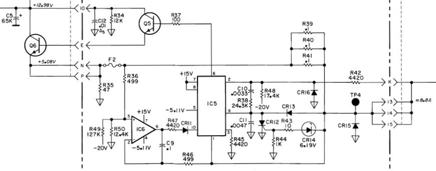
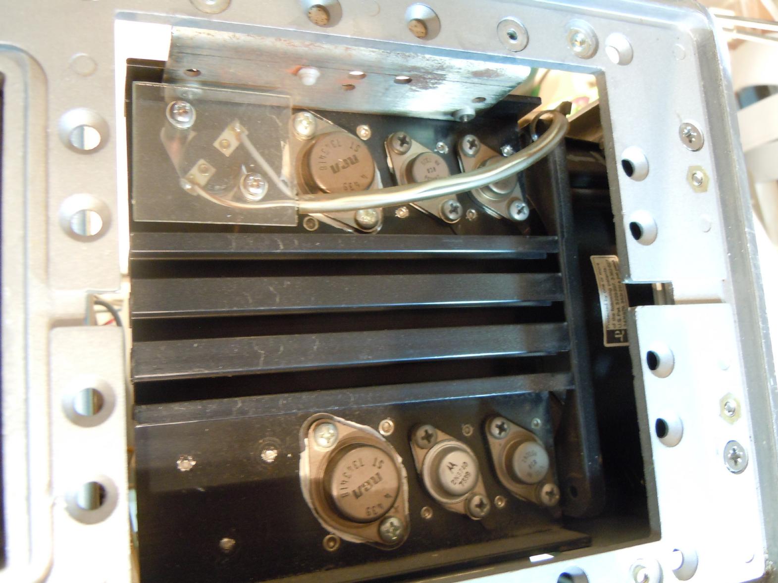
The section delivering the +5 V supply for the digital circuits of the HP3330B is shown on the right. It turned out that Q6 (a 2N3055) was defective. Replacing it yielded... Not quite +5 V - in fact the output was about +4.2 which was enough to display some garbage but not enough for any real operation. So something else had to be defective, too. (The picture below left shows the 2N3055 which is accessible behind the right side of the instrument.) |
|
|
I noticed that the voltage sometimes increased to about +4.7 V and then turned out to vary with the number of display sections turned on - somewhere was a load dependent voltage drop. It turned out that all three 0.1 Ohm resistors on the power supply board had bad solder joints - resoldering them resolved that problem. The +5 V supply was now rock solid and measuring the voltage drop over these resistors showed that the total current drawn was about 8.5 A. |
|
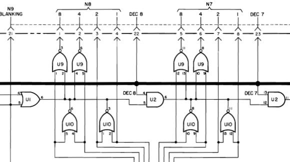
Now it was time to have a close look at the instrument - entering a frequency like 1 MHz displayed complete garbage in the two digits second and third to the left of the frequency display. *sigh* Another bug. Both digits displayed strange values - entering different numbers and shifting them through the display showed that both digits were differently erroneuous. I hoped that it was only a display problem and not a problem rooted deeply in the microcoded control logic, so I concentrated on the display section of the control unit. The schematic on the left shows the section driving these digits. |
|
Since I have no extender card, I could not easily measure on the display controller board, but my first guess was that U9 might be the culprit. According to the schematic this is a quad NOR gate in DTL technology - something I unfortunately do not have in my spare parts collection. But wait - nothing in the circuit needs the wired OR capability of the DTL outputs, so why not replace it with a quad NOR TTL chip? Naturally something like the 74LS02 comes to the mind - but its pin out is completely different (and quite awkward if one asks me) from that of the DTL chip. But bending all its pins to its top side and reversing +V and GND one gets a replacement part for the DTL quad NOR chip. As shown on the right. It turned out that my guess was not bad since both digits now behaved consistently but still erroneously! But at least this was a step in the right direction. Carefully entering number patterns and noting the output bit patterns on the display, I realized that something was really fishy. My friend Arno brought me on the track - believe it or not, but the HP schematic is WRONG! U9 is not a quad NOR, but a quad OR gate! Replacing my carefully made replacement with a simple 74LS32 was simple and... did not cure the problem. The display was still erroneous... |
|
|
After a lot of thinking I came to the conclusing that U10 might be defective, too. Replaing it (this time it really :-) is a quad NOR as the parts list shows) was not so simple since the wired OR capability is used, so I needed a quad NOR with open collector output. *sigh* The best solution I could think of was to stack a 74LS32 quad OR and a 74LS06 open collector inverter and create my own open collector quad NOR - the result is shown on the left side. Unfortunately there is not enough clearing between the display controller board A5 and its enclosure for an IC socket and two ICs stacked on each other, so I had to directly solder in this contraption. Believe it or not - the display worked immediately after this change. I could enter any frequencies and they were displayed correctly! |
|
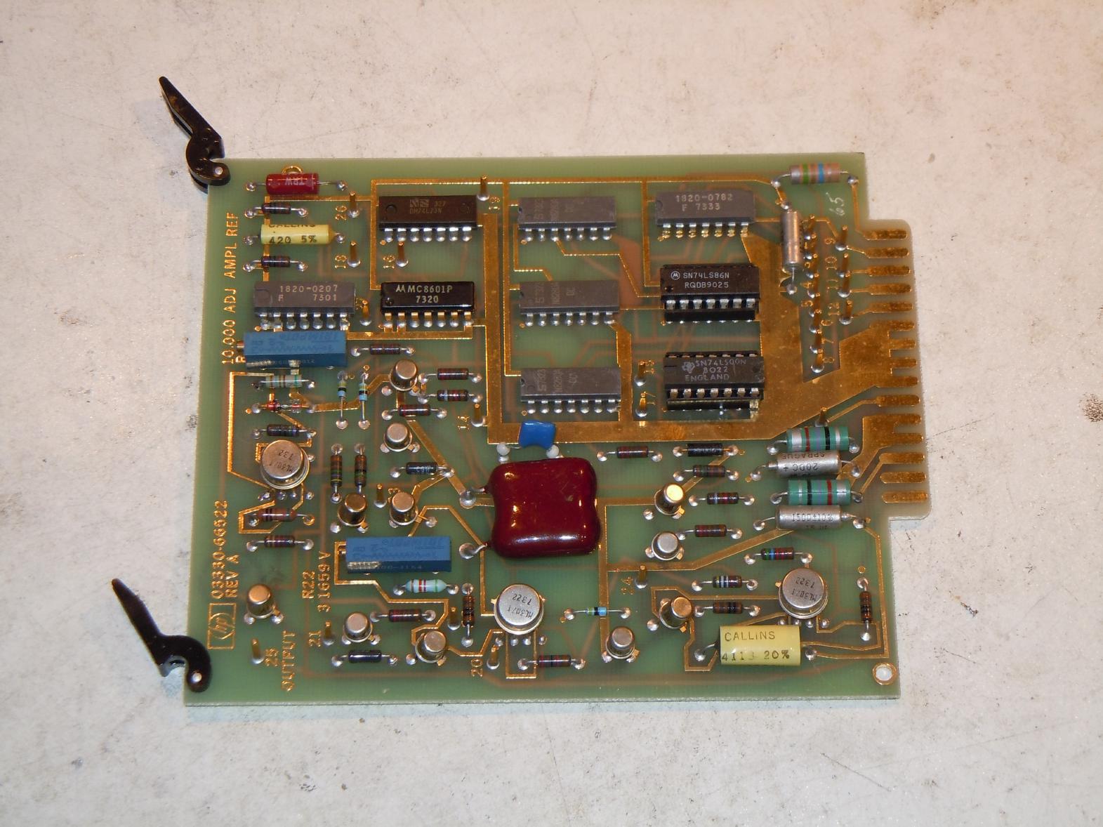
Unfortunately this was not the last error - there was no output signal at all from the synthesizer! Tracing the various signals that are used to drive the synthesizer it turned out that the problem was in the amplitude control circuit, something I was and still am quite glad about since this part of the circuitry uses mostly standard parts and should be easy to repair, or so I thought. The amplitude control is quite interesting - there are four BCD coded digits used for amplitude control. The most significant digit controls a relay based attenuator which worked correctly as some measurements showed. The three remaining digits control a digital analog converter which in turn delivers an analog control voltage for the fine grain amplitude control. The picture on the right shows this board, A26. Repairing A26 caused some of my hair to get grey, I think. |
|
|
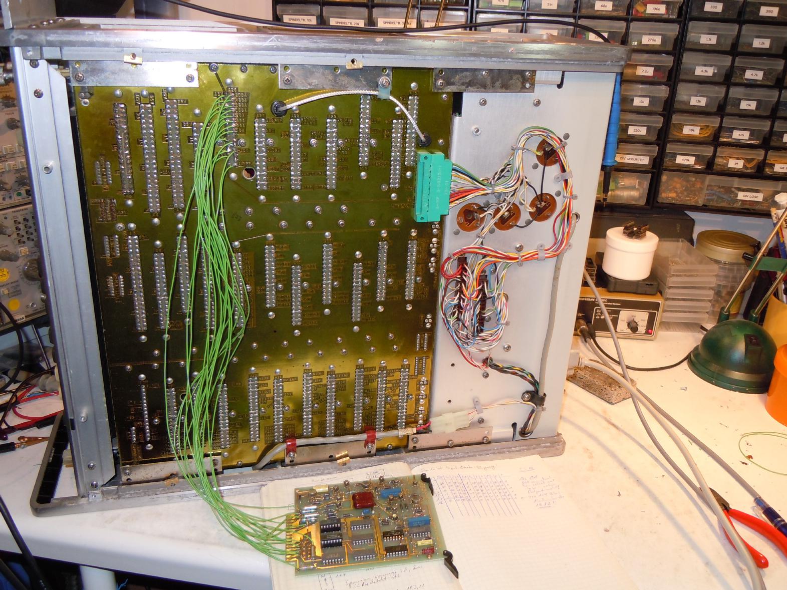
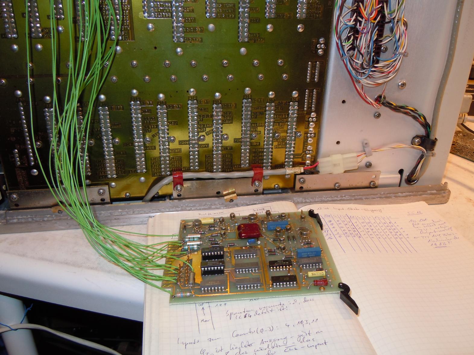
The first and simplest problem was (and still is) that I do not have an extender board. Without this tool it would have been just horrible to debug A26 in its natural habitat, so I decided to make my own hand wired extender using 20 pieces of wire. The result shown on the left is not pretty but it worked great and helped a lot. (Please note the hand written table in my note book below the A26 board - I wrote down a lot of bit patterns during the debugging phase - all in all I filled 18 pages in my notebook with this project!) |
|
So how does A26 work? Its principle of operation is quite classical: A capacitor is charged by a precise current reference and is then discharged for a varying amount of time that is determined by the bit pattern at the input of A26. The remaining voltage over this capacitor is then transferred to a sample and hold circuit. Basically A26 converts a bit pattern into a pulse (pause) width modulated signal to control the time the capacitor discharges through a known resistor. After storing the remaining voltage into the S&H stage the capacitor is charged again etc. The picture below shows the overall schematic of A26.

|
|
|
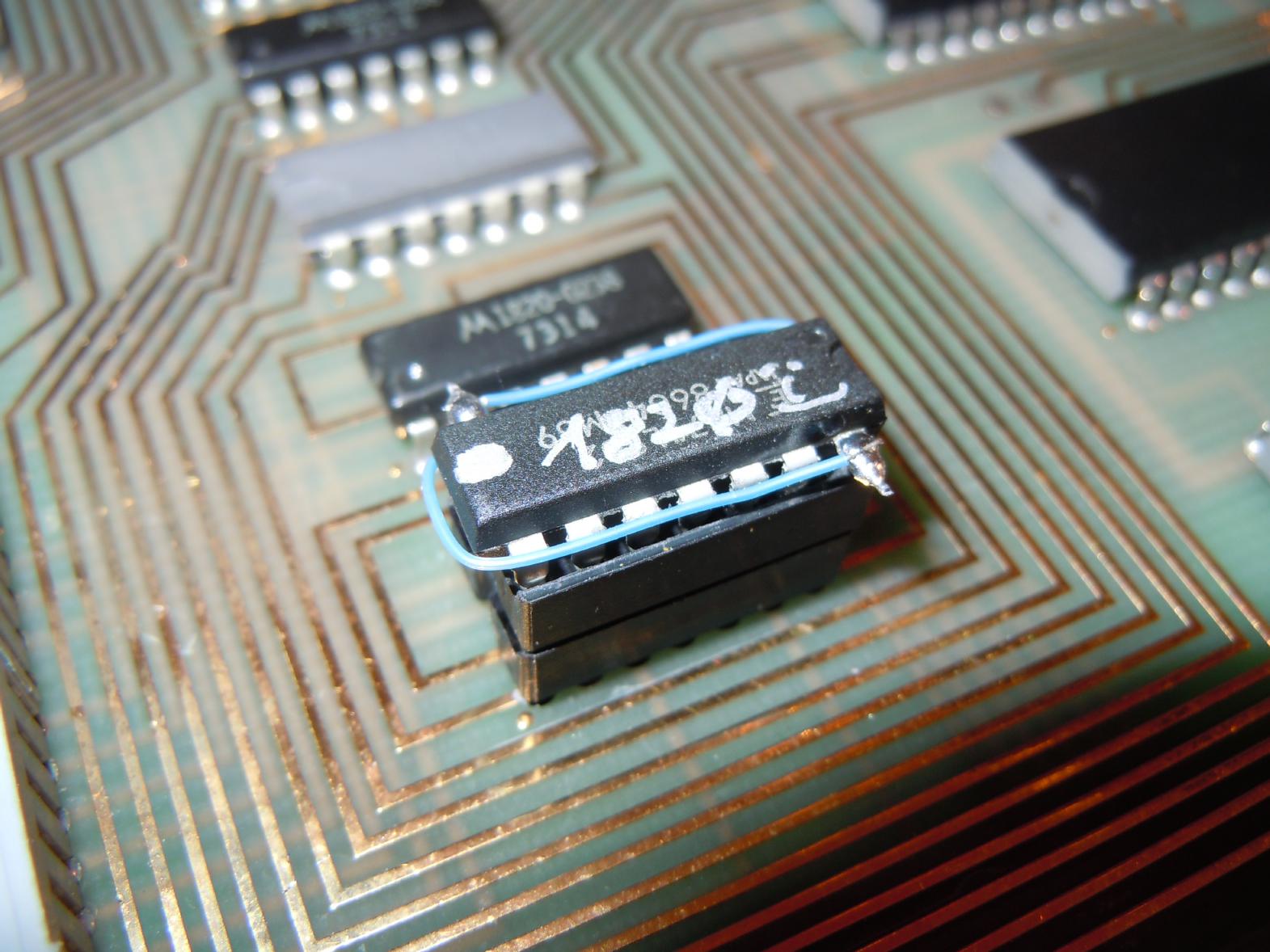
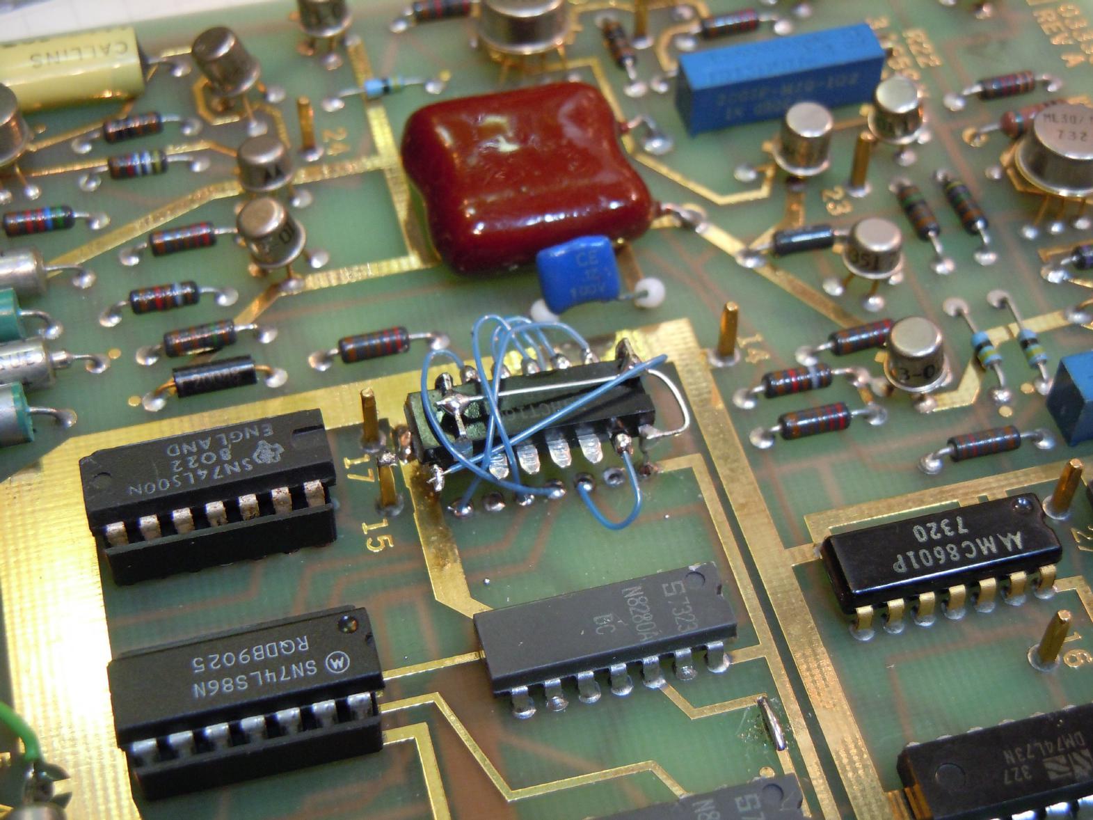
The digital input section of A26 is quite tricky - every four bit BCD input is preprocessed with a triple input NOR gate, a XOR gate and an inverter. (Why? Because it needs complemented numbers since it controls an attenuator and not an amplifier - the three gate solution is quite tricky and elegant.) Comparing the inputs and outputs to these three gate sections showed that the inverter (in fact a quad NAND gate) and the quad XOR were both defective. The picture on the right shows the replacement parts mounted in IC sockets (I used a 74LS00 and a 74LS86). Unfortunately this was not the only problem. I decided to have a deeper look at the three decimal divider stages based on 8280 DTL decimal divider chips. Starting with the least significant digit I checked the behaviour of the divider with a logic analyzer. It turned out that the first of these dividers did not work at all which was where my following problems started. |
|
|
The main problem was how to replace a 8280 decimal divider - I had nothing comparable in my parts collection. A friend suggested a 74176 which was next to unobtainable and thus not a solution. He also suggested the 74HCT160 and by sheer luck I was able to buy some 74HCT160 for 20 Cents each. So I replaced the first 8280 divider with a 74HCT160 decimal divider. I have to admit that it was late night, and I did not really think about what I was doing here. Of course, the simple replacement shown on the left did not work, but why? There just was no output pulse at all. Why? Time to get some sleep and think it over. The next morning I realized my stupid error: The original 8280 DTL chip featured an asynchronous load while the 74HCT160 has a synchronous load that requires a clock pulse during /LD being low. Unfortunately the strobe logic on A26 prevents exactly this - there is no clock pulse at all during strobe time and thus the 74HCT160 does not work as a replacement, or does it? |
|
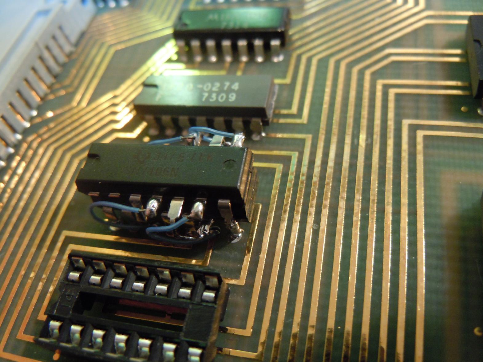
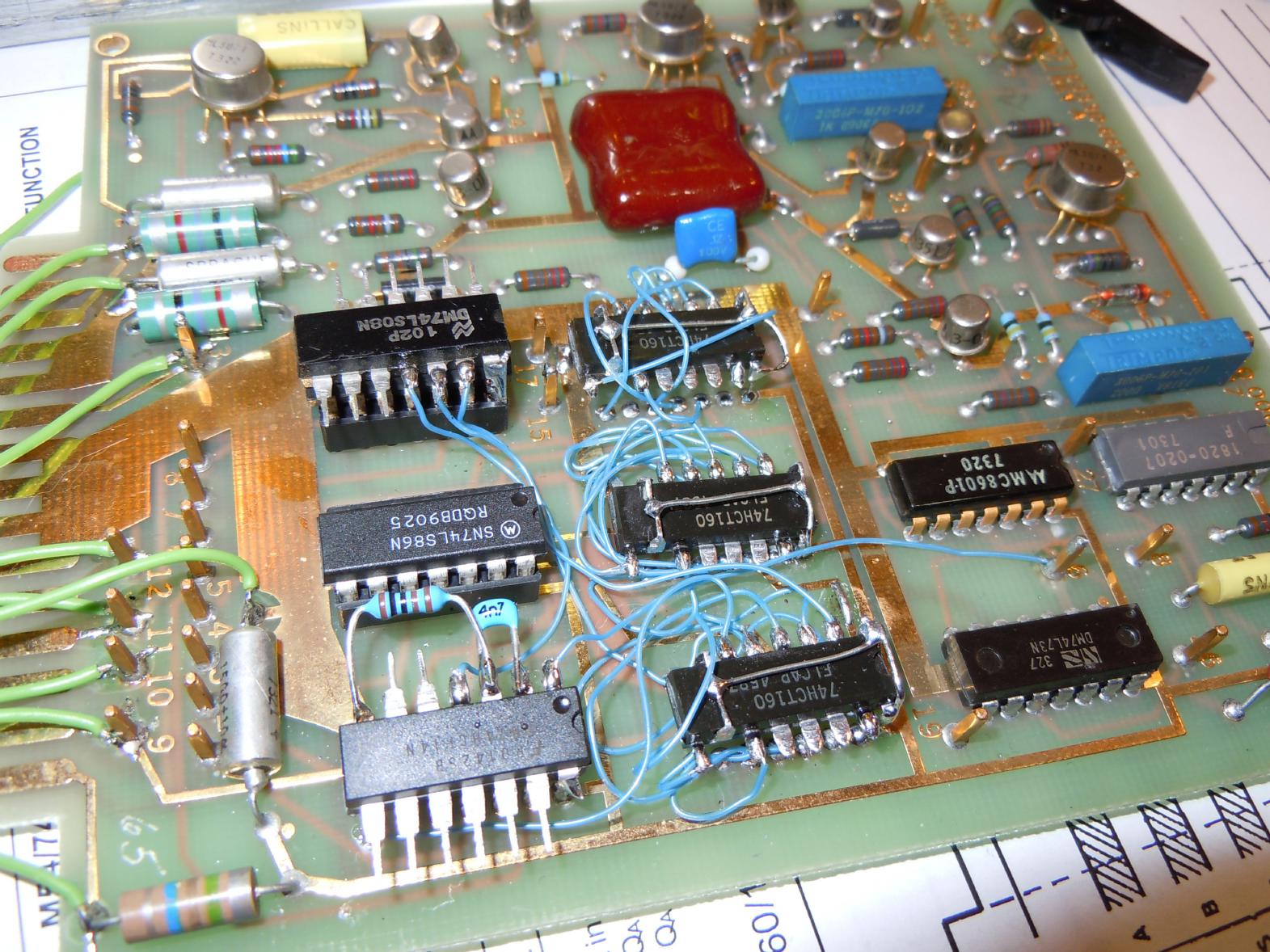
To make a rather long story short: I had to generate a single artificial clock pulse during the strobe time of the divider chips on A26. For this purpose I differentiated the /LD signal with a resistor-capacitor combination, generating an active low signal of short duration that gets low during /LD being low. Combining this signal with the original clock signal with a 74LS08 AND gate yields the desired effect, a single additional clock cycle just for loading the 74HCT160 chips with the necessary bit pattern. Unfortunately it turned out that all three 8280 chips were defective. (Quite strange: The one in the middle had a crack through its case and came apart during removing the IC.) This was where I made my next error: I just replaced the 8280 dividers by 74HCT160 - it took a moment for me to realize that this was plain wrong since cascading 74HCT160 works completely different than cascading 8280 chips: While the 8280 were chained using their 9-output, the 74HCT160 are chained using their TE inputs and carry outputs. Changing my erroneous circuitry was simple. |
|
|
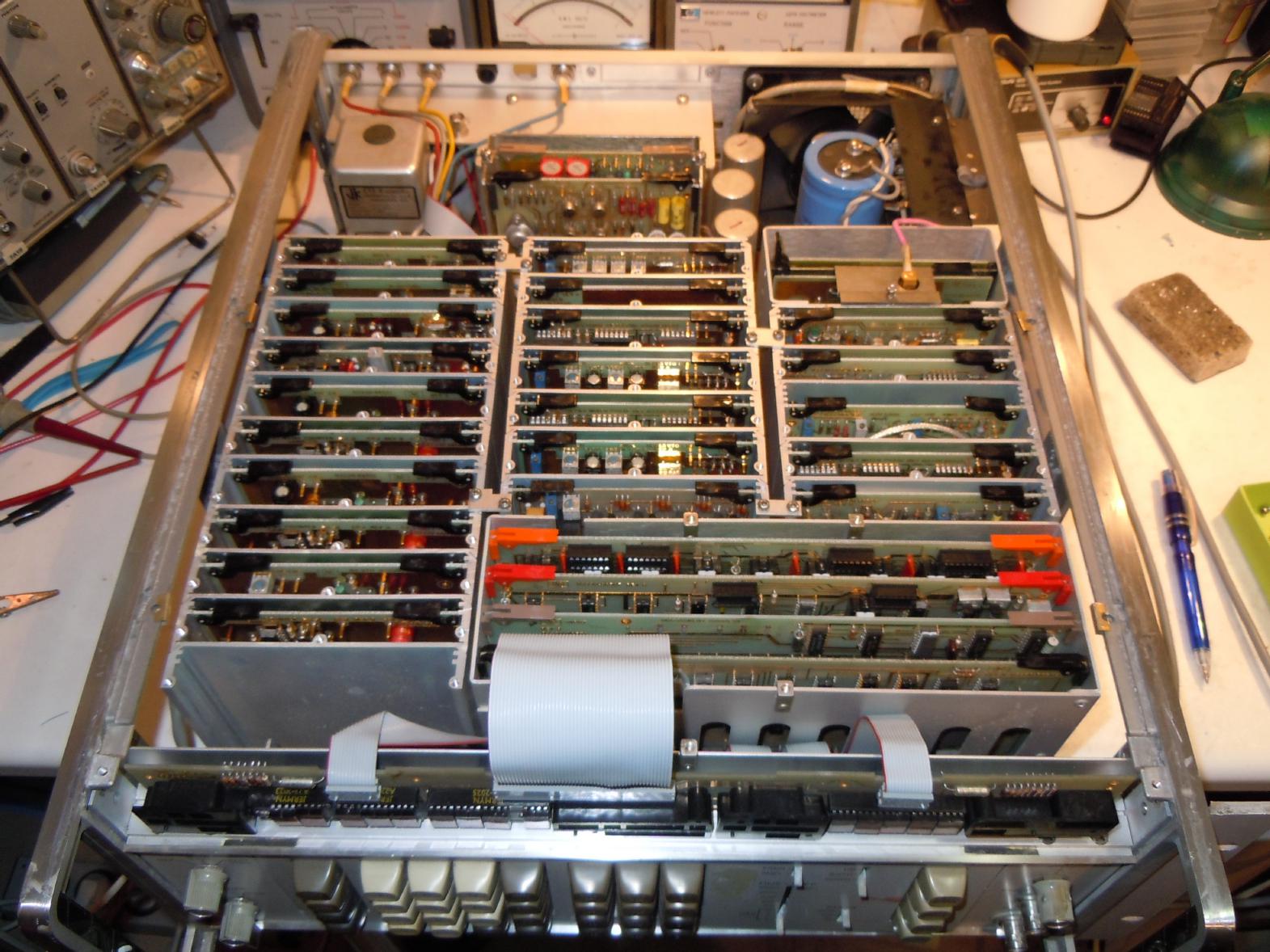
After fixing this wiring error I was pretty sure that the instrument would now work. How wrong I was... Sometimes amplitude settings were OK, sometimes they were wrong by a rather large amount... Careful probing showed that a connection on A26 was bad - the output of one of the three input NOR gates was not "really" connected to the appropriate input of the corresponding divider chip. This is really strange since the board looks quite beautiful and there is no sign of any physical damage at all. Resoldering the two connections did not cure the problem - the connection within the multilayer board was just not stable. I then added an additional wire wrap wire and the problem was cured. Unfortunately this wasn't the last bug: The least significant amplitude digit turned out to be in error for the digits 8 and 9. 8 and 9? Should the MSB be missing? Yes! Another defective connection - this time on the multilayer backplane. I fixed this with yet another wire wrap wire. The picture on the left shows the repaired and still opened synthesizer - isn't it a beauty? |
|
Since then the synthesizer works like a charm and I have learned quite some lessons:
| |