|
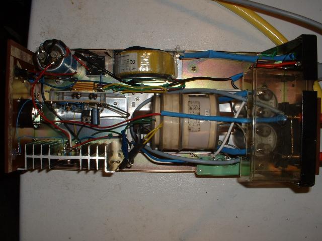
A few months ago I bought a couple of new HeNe laser tubes from a local electronics shop since these were incredibly inexepensive with about 7 EUR per piece. These tubes lay around in my workshop for quite a while since I had no suitable power supply for them. When I found some spare time I decided it was time to go and learn about lasers and high voltage electronics and started to build a simple, yet useful power supply from scratch and from parts which were available at no cost at the moment. The result of this attempt may be seen on the left - the frame has been an enclosure for an old 5.25 inch hard disk drive in its former life. Since I had not much experience with high voltage electronics I decided to stay on the safe side and develop a circuit working from a low input voltage so the only way to kill myself would be the high voltage output but not the input as well. :-) |
|
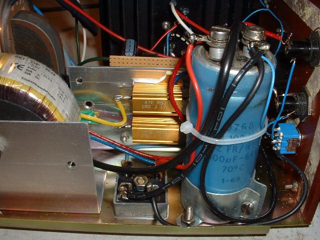
The picture on the right shows part of the (input) power supply converting the mains (240V) to something not so dangerous: 24V. :-) On the left the toroidal transformer can be seen - since it has two output windings of 24V each which have to be connected in parallel to achieve the necessary current I used two high power resistors for paralleling them and to level small differences of the two windings. The output of this is rectified by a simple Greatz bridge and then filtered by the very stylish (read: old :-) ) blue electrolytic capacitor seen on the right. In the background the black cooling fin of the voltage regulator (7824) and the switching transistor (2N3055) can be seen as well. |
|
|
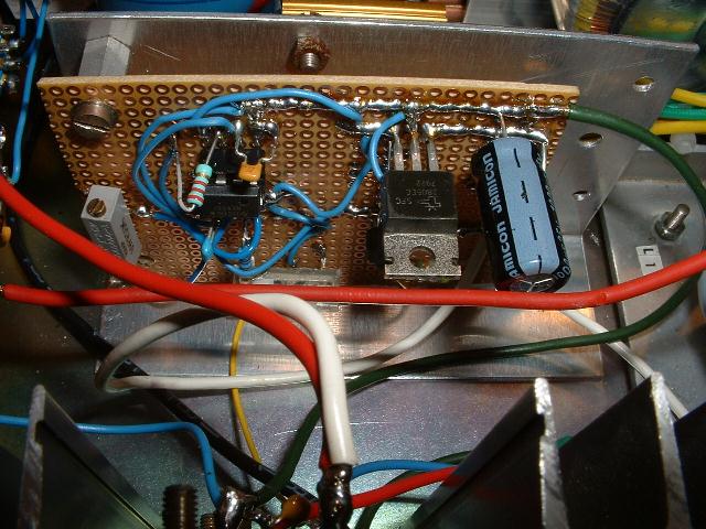
The high voltage generation is quite simple - the high voltage transformer which can be seen in the middle of the overview picture (the first picture on this page), which has been salvaged from scrap (it was part of an old mass spectrometer), has a nominal input voltage of 24V. Thus the 24V delivered by the power supply are then applied to this transformer by means of a power transistor (a 2N3055) which is controlled by a simple oscillator built around an NE555 chip. This oscillator can be seen in the picture on the left. |
|
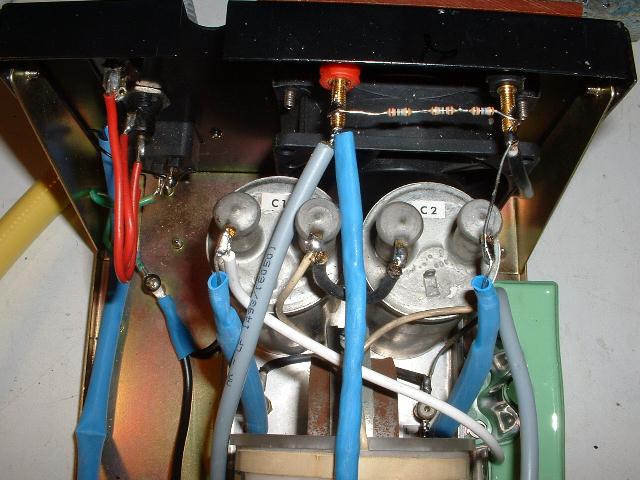
The output voltage of the high voltage transformer then passes a voltage doubler built from two (old) high voltage capacitors of 1uF each which can be seen on the right. The two blue shrink wrapped parts leading to the capacitors are in the fact the two rectifiers built from a chain of four 1N4007 diodes, each. The shrink wrap is necessary to prevent arcing. Accross the output jacks a small bleeder consisting of three 1M resistors can be seen. This is necessary to ensure that the voltage doubler capacitors do not store hazardous energy after the device has been powered down. This system generates an output voltage of about 2kV (without an external load - apart from the bleeder resistors), depending on the frequency and pulse width of the oscillator. |
|

|
The main problem with a HeNe tube is the required starting voltage which is much higher than the voltage necessary to maintain the lasing. To generate this starting voltage I use a simple high voltage cascade as may be found in an old TV set which can be seen on the right side of the picture on the left (the green device). This cascade is connected with one lead to the unrectified an undoubled output of the high voltage transformer by a series resistor of 22M. The other input lead is connected to the output of the voltage doubler. When the tube is not lasing its resistance is high like an open circuit. This results in the cascade building up a rather high voltage (up to 10kV without load!) since it is fed by the 22M resistor. When this voltage reaches the ignition voltage of the tube which may be around 6 kV the cascade gets discharged and the voltage doubler takes over supplying the lasing voltage of about 1.5 kV. |
|
Since high voltages like these really make me nervous I decided to shield the entire high voltage section with some plastic as shown in the picture on the right. The two security banana plugs used for connecting the HeNe laser tube may be seen, too. Note that the shielding was in fact necessary to prevent arcing whith the metal lid installed on the enclosure. |

|

|
The front panel of the power supply is rather simple in style and shown on the left. The dominant feature is a voltage display made from a 100uA instrument with appropriate series resistors (a long chain of 10M resistors and some different values for fine tuning - this was the first occasion I was really happy about my 40kV high voltage probe. :-) The switch and the fuses on the left are for the secondary of the toroidal transformer only. The primary side has its fuse on the back panel of the power supply. |
|
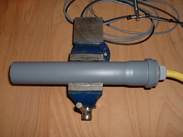
When playing with a naked HeNe tube it gets quite obvious that such a tube is a delicate thing which even makes attaching the power leads quite complicated. By the way - do not forget that a HeNe tube has a negative resistance when lasing so it definitely needs a series resistor to limit the current flowing through it. Normally this is about 75k - in my case I had to use 100k since I did not have a 75k resistor at hand. The picture on the right shows the tube in its enclosure - I used 5cm standard water pipe from the hardware store. Since I am really paranoid when it comes to high voltages I decided to enclose the power leads in a piece of garden hose entering the device on the right. :-) |
|
|
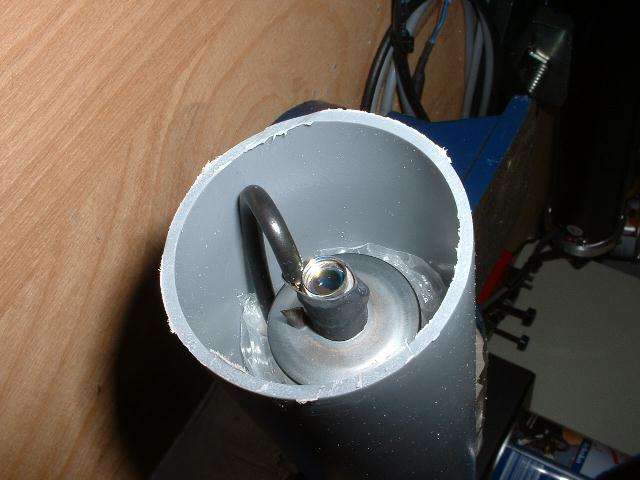
Mounting the tube (round by default :-) ) is not all too simple. After some experiments I decided to use foil used for packing delicate materials as my main mounting. The picture on the left shows the tube wrapped with this foil and pushed into the water tubing. The output mirror is clearly visible as is the cathode lead secured by shrink wrap foil. All in all the tubes turned out to have about 1mW. They need 6kV to ignite and about 1.5kV for continuous lasing. The oscillator has been set accordingly so the output voltage matches these requirements quite closely. Note that there is no regulation at all - the current is limited by the series resistor of the tube and the resistance of the voltage doubler and the cascade. |