|
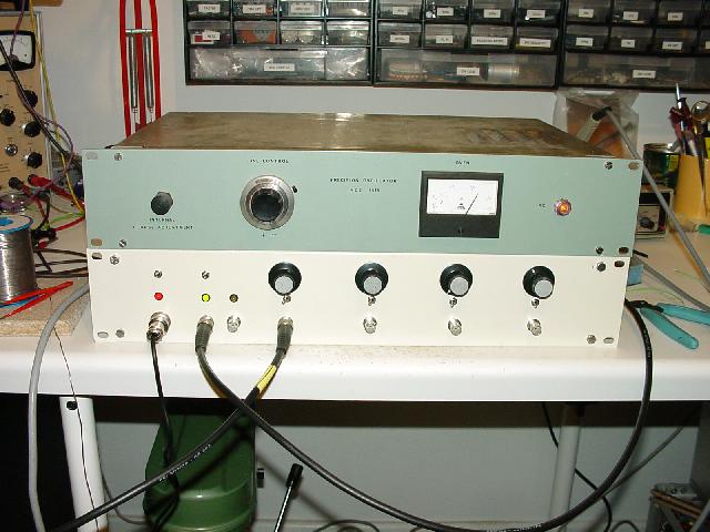
If one has two or more AD converters or magnetometers or other data sources continuosly running, the unavoidable slow clock drift of these not interlocked devices becomes more and more annoying since it gets difficult to correlate data sets from different converters. Since my seismometer hut has now two 8 channel, 16 bit AD converters and a magnetometer which are in operation all the time I decided to build a small clock generator which allows me to feed different scan rates into the devices while sill maintaining an interlock between all the clock signals. This task is quite simple to accomplish by employing a chain of dividers whith appropriate taps where the desired scan rate signals can be picked up. The setup on the left consists of the divider circuitry housed in the lower enclosure, while the upper enclosure is an HCD 1519 frequency standard which I acquired very cheap (approx. 40 EUR) from scrap. This frequency standard generates a 1MHz sinusoidal output signal which is used as the input for the divider chain. |
|
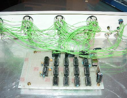
The circuit board containing all the base 10 and base 2 dividers can be seen on the right: The 1MHz input signal is divided to yield eleven outputs of 100kHz, 10kHz, 1kHz, 100Hz, 50Hz, 25Hz, 12.5Hz, 10Hz, 1Hz, 10 seconds and 60 seconds which are connected to four rotary switches which are used to select one of these frequencies for output. This setup allows the generation of four clock signals with different frequencies which are always interlocked since they are derived from the same (and by the way very stable) input signal. Each of these four selected output signals is fed into a monoflop consisting of half of a 74LS123 to ensure a proper output signal form for each selected frequency. These pulses are then amplified by an open collector driver 74LS06 and routed to their appropriate BNC output jacks on the front panel. |
|
|
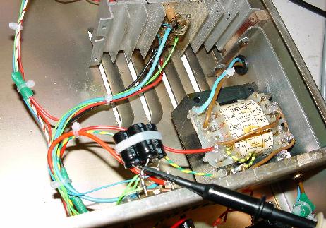
Unfortunately the HCD 1519 frequency standard which I am so proud of turned out to be the most problematic part of my clock generator: During a quite lenghty test run (my intention was to check the long term stability of the generator and to adjust its frequency to as close to 1MHz as possible) when I was not in the room but on my X-terminal typing, everything suddenly went off! It was pitch dark and when I opened the door I smelled a horrible malodor from molten pitch. With a flashlight I entered the room where the clock generator was running and could not even breathe! When I could breathe again after a long time of ventilation, I entered the room and inspected the frequency standard. Its enclosure was so hot I could hardly pick it up and it turned out that a design bug (not a flaw) had nearly caused a fire to start: Obviously the rectifier bridge has been shorted which caused the main transformer to overheat. Unfortunately the DC fuse was located behind (!) the rectifier and thus was not able to save the transformer from being destroyed. It got so hot that the pitch it was filled with not only started to melt away but to crack the transformer enclosure. About 100g of pitch run out of the transformer until my FI protection switched the mains off. Luckily the frequency standard itself has not been damaged and after cleaning everything (which was a horrible task due to the malodor of the pitch and wax) I build a new power supply which can be seen on the left. And now the DC fuse is no DC fuse any more and sits directly between the transformer and the rectifier! :-) |