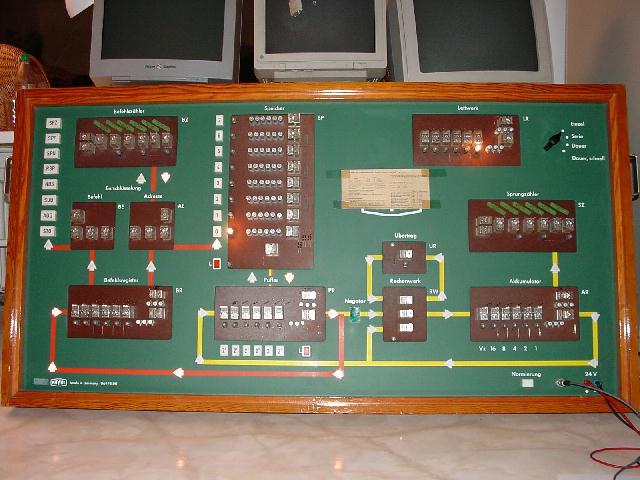
Left from the middle of the machine the memory system
can be seen - it consists of eight memory locations
of six bits each. Every bit is stored in an electrolytic
condensator, the selection of a single storage location
is done by a relay (on the right of the condensator
bank lines).
Below the memory bank is the central buffer register -
all accesses from and to memory are done via this
register. It is connected with the ALU on the right
and the instruction decoder on the left.
The light bulbs in the upper left of the machine show
which instruction has been decoded recently. Also
located here are the address register for controlling
all memory accesses and the program counter.
The right half of the computer contains the (already
mentioned) serial ALU, the six bit accumulator, a
branch counter and the control logic. The switch in the
upper right corner is used to select the desired run
mode of the machine. It can be operated in single step
mode (microsteps or instruction steps), in slow and
fast mode.
In fast mode, the machine is capable of performing
approximately one instruction per second.
Numerical values are represented in 1-complement (like
in old CDC machines beginning with the CDC-1604 and
ending with the CDC-7600), i.e. the negative form of
a number is generated by inverting all bits of the
number. Note that there is no correction term of +1 like
in two's complement, so there are in fact two nulls in
in this machine - +0 (000000) and -0 (111111).